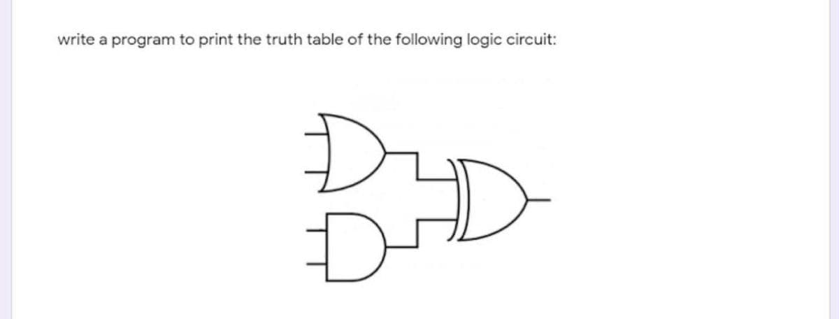
write a program to print the truth table of the following logic circuit:


Q: A logic circuit realizes the function F(A,B,C,D) = A' B' + A' C D + A C' D+ A B' D'. Assuming that A…
A: Actually, given question regarding Boolean function:
Q: A B F From the above logic circuit, F value is o when a. All options are correct O b. A=0, B=0, C=1…
A: Answer is : All options are correct
Q: write a program to print the truth table of the following logic circuit: Using c++ D-
A: #include<iostream> using namespace std; int main(){ cout<<"Truth table:…
Q: Q1: Draw the circuit for this Boolean expression after simplification ,then Find the truth table…
A: The answer is in below steps:
Q: A logic circuit that selects and routes any number of inputs to a single output is?
A: a logic circuit that selects and routes any number of inputs to single output is Choose the…
Q: Write the Boolean Expression for the output of the following logic systems.
A:
Q: Write a handwritingreport including a short description about the circuit(including function,…
A:
Q: Write the Boolean equations and draw the logic diagram of the circuit whose outputs are defined by…
A:
Q: a. Complete the truth table for the logic circuit shown below. b. Write the Boolean expression for…
A: As per our guidelines, we are supposed to answer only one question. Kindly repost the remaining…
Q: DRAW THE CIRCUIT AND CONSTRUCT THE TRUTH TABLE OF THE EXPRESSION G=(((A B' C')' + B C)' A B')'
A: Given function is, G=(((A B' C')' + B C)' A B')' The variables present in the function are A, B and…
Q: Draw the combinational circuit that directly implements the following Boolean expression:F(x, y, z)…
A: Step 1 : The given logical expression is as below : F(x, y, z) = x + xy + y′z. We can notice that in…
Q: Draw logic diagrams of the circuits that implement the original and simplified expressions…
A: Draw logic diagrams of the circuits that implement the original and simplified expressions…
Q: Write Boolean expressions for the circuits given below
A: The given diagram is a 3 variable function with inputs as function of A, B and C and output as Q.
Q: Draw the logic circuit represented by the following expression: a) (A+ C)B) + (CD + Ã) + (BD) b) AB…
A:
Q: Implement the following equations using logic gates and write down the truth tables. 1. F= A xnor B'…
A:
Q: Draw the combinational circuit that directly implements the Boolean expression:F(x, y, z) =…
A: BOOLEAN expressions can be expressed by the combinational logic circuit. Here the given expression…
Q: Create 2 logic diagrams with at least 4 inputs using at least 3 logic gates and provide their…
A: Two logic diagrams along with their truth table is given below.
Q: b d y2 f
A: The answer for the above given question is given below:
Q: Write the Boolean equations and draw the logic diagram of the circuit whose outputs are defined by…
A: First we have to write the f1 and f2 to get the boolean equation. For that, wherever the value is 1…
Q: Q1/ write a program to draw a truth table of the following logic circuit: using iostream
A:
Q: F = (A+ B) (A+B)
A: Find Your Answer Below
Q: Question: Implement the following Logic Circuit using C++ program. A, B, C, and D are the input bits…
A: Input : Given the boolean values of A, B, C, D. Output : The output value of F.
Q: Q1/ write a program to draw a truth table of the following logic circuit: C++
A: In this question, we have to print the truth table of the given circuit. This circuit takes two…
Q: Implement the following Logic Circuit using C++. A, B, C, and D are the input bits while F is the…
A: #include <iostream> using namespace std; int main() { int a,b,c,d,f; cout<<"enter…
Q: V. Problem Šolving: 1. Find the truth table for the logic circuit shown below. Авс F 0 0 0 0 0 1 0 1…
A: The gates that are shown in the diagram are said to be XOR gates These gates take 2 bits as inputs…
Q: A. Write the Boolean equation directly from the following circuit. B. Create the truth table for…
A: Here in this question we have given a circuit we have asked to derive boolean equation from…
Q: 2. Find the Boolean expression for the logic circuit shown below. Finally simulate the circuit with…
A: We have to find out the boolean expression for the given logic circuit and also draw it with only 2…
Q: Logic Circuit using C++. A, B, C, and D are th
A: Implement the following Logic Circuit using C++. A, B, C, and D are the input bits while F is the…
Q: The logic circuit below is supposed to be designed to produce the truth table also shown below.…
A: The truth table works like this; When x value goes from not gate, the value is inverted. Also,…
Q: The boolean expression for the below logic circuit is equivalent to * A
A: In the above diagram A and B are two inputs and A.B
Q: 4-Draw the logic circuit represented the following truth table. INPUT A INPUT B INPUT C OUTPUT P 1 1…
A: Solution 4 For the high output P(value 1), P=A¯ B¯ C¯ + A¯ B¯ C Disclaimer: Since you have…
Q: Draw the combinational circuit that directly implements the Boolean expression: F(x, y, z) = xyz +…
A: The combinational circuit for the given Boolean expression is as follows,
Q: Write a handwritingreport including a short description about the circuit(including function,…
A: Answer is given below .
Q: Derive the Boolean expression for the logic circuit shown below: Select one: a. C(A + B)DE b. A+…
A: In Boolean Algebra the OR function is the equivalent of addition so its output state represents the…
Q: Build the circuit shown below and complete the truth table to show correct operation. Input A Input…
A: Equation for A<B: F = A'B Truth table for A<B: A B A' Output 0 0 1 0 0 1 1 1 1 0 0 0…
Q: Find the output of the circuit corresponding to the input P = 0, Q = 0, and R = 1. Write the Boolean…
A: Given: - P = 0 Q = 0 R = 0 S = 1 Hence, Output is 1.
Q: Draw a logic circuit that would process all subtraction operation using simple addition
A: To perform the given task, let us first understand the logic behind "Subtraction by addition".To…
Q: What Boolean function does the following circuit represent? B. A -Y
A:
Q: Q1/ write a program to draw a truth table of the following logic circuit: with c++
A: Answer of the given question is C++: OUTPUT
Q: A FIGURE 4-56 14. Draw the logic circuit represented by each of the following expressions: (a) A…
A: As per the company norms and guidelines we are providing first three questions answers only so again…
Q: Q2. Write a program in C++ language to find the result of this logic circuit: A B
A: It is defined as a direct descendant of C programming language with additional features such as type…
Q: Consider the following logic circuit. A B F a) Write the Boolean function F(A, B, C).
A: A Boolean function is a function that has n variables or entries, so it has 2n possible combinations…
Q: 1. Find the truth table for the logic circuit shown below. Авс F 0 0 0 0 0 1 0 1 0 0 1 1 10 0 1 0 1…
A: The gates that are shown in diagram are said to be XOR gates These gates takes 2 bits as inputs and…
Q: Write a Verilog code for the following circuit a t1 G1 b G3 C G2 d
A: Verilog code for given diagram.
Q: Q1/ write a program to draw a truth table of the following logic circuit: Ву с++
A: Provided the C++ program to draw a truth table of the above given logic circuit is given as shown…
Q: Which is the correct boolean expression for the logic circuit given below? DA.B A +C Select one: O…
A: AND Gate does the multiplication of the inputs three inputs for last AND Gate is A.B A+B A+C…
Q: Give both a logic circuit diagram and a truth table for the following logic expression: ¬(A ∨ B) ∧…
A: Solution:-
Q: Q1. Write the expression and show the behavior of the following circuit with a truth table (3.5…
A: EXPRESSION: The AND gate is performed between the input A and B. The NOR gate is performed between…
Q: The boolean expression for the below logic circuit is equivalent to * A B C (AB) C' A'C+B'C+AB A…
A: The gates given in logical circuit are: NAND gate XOR gate XNOR gate

Step by step
Solved in 4 steps with 3 images

- write a program to print the truth table of the following logic circuita) Implement the following Logic Circuit using C++. A, B, C, and D are the input bits while F is the output bit function. A computer circuit is to generate a 1 if the decimal value of the binary number X3X2X1X0 is either 0, 2, 3, 6, 10, 11, or 14. Write a truth table representing the above logic Write a boolean expression for F(X3X2X1X0)
- Draw the combinational circuit that directly implements the following Boolean expression:F(x, y, z) = x + xy + y′zDraw a logic circuit diagram of the below expression. AB'+ BC' it would be great help..if you provide the truth table also..Write the Boolean equations and draw the logic diagram of the circuit whose outputs are defined by the following truth table: Table P2.27f 1 f 2 a b c1 1 0 0 00 1 0 0 11 0 0 1 01 1 0 1 11 0 1 0 00 1 1 0 11 0 1 1 1
- Draw the non-abbreviated logic diagram for the following Boolean expressions. (You may use XOR gates.) A) ((a’)’)’C) a’b + ab’F) ((ab XOR b’) + a’b)’K) (abc’) + (a’ b’ c’)’N) (((a + b)’ + c)’ + d)’Create a non-abbreviated logic diagram for the following Boolean Expressions. You can use all gates. a’b + ab’ ((ab)’(b’c)’ + a’b’c’) (a +b)(a’ + c)(b’ + c’)Draw the circuit for the following Boolean expression: P = (X and Y) or (not X or Z)
- Identify the following logic gate by name, and write the truth table with Boolean expression. Just answer without explanation please1. Find the truth table for the logic circuit shown below. Write the Boolean expression: ____________________Draw the non-abbreviated logic diagram for the following Boolean expressions. (You may use XOR gates.) K) (abc’) + (a’ b’ c’)’N) (((a + b)’ + c)’ + d)’