Mechanics of Materials (10th Edition)
10th Edition
ISBN: 9780134319650
Author: Russell C. Hibbeler
Publisher: PEARSON
bartleby

Concept explainers

bartleby

Videos

Textbook Question
Book Icon
Chapter 1, Problem 1.1RP

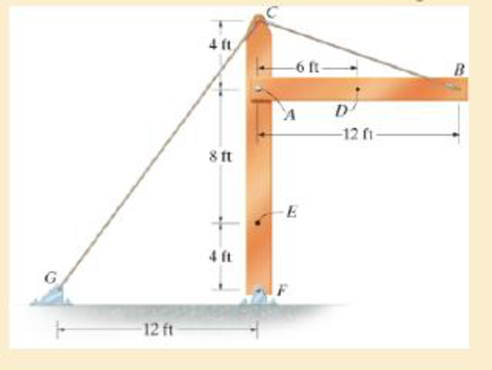
The beam AB is pin supported at A and supported by a cable BC. A separate cable CG is used to hold up the frame. If AB weighs 120 lb/ft and the column FC has a weight of 180 lb/ft, determine the resultant internal loadings acting on cross sections located at points D and E.

Chapter 1, Problem 1.1RP, The beam AB is pin supported at A and supported by a cable BC. A separate cable CG is used to hold

Expert Solution & Answer
Check Mark
To determine
The resultant internal loadings acting on cross sections located at D and E.

Answer to Problem 1.1RP

The resultant internal loadings at cross section at D are ND=2.16kip,VD=0_, and MD=2.16kipft_.

The resultant internal loadings at cross section at E are NE=4.32kip,VE=0.54kip_, and ME=2.16kipft_.

Explanation of Solution

Given information:

The beam AB is pin supported at A and supported by a cable BC.

The weight of the beam AB is 120lb/ft.

The weight of the column FC is 180lb/ft.

Calculation:

Find the loading at the center of the beam AB (PAB):

PAB=Weight of beamAB×LengthofbeamAB

Substitute 120lb/ft for the weight of beam AB and 12 ft for the length of beam AB.

PAB=120×12=1,440lb

Convert the unit from lb to kip.

PAB=1,440lb×1kip1,000lb=1.44kip

Sketch the Free Body Diagram of the beam AB shown in Figure 1.
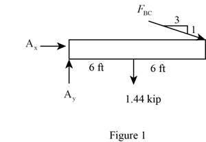
Mechanics of Materials (10th Edition), Chapter 1, Problem 1.1RP , additional homework tip  1

Refer to Figure 1.

Find the angle of cable BC to the horizontal (θ):

sinθ=112+32sinθ=13.1623θ=sin1(0.3162)θ=18.43°

Find the tension in cable BC as shown below.

Take moment about A is Equal to zero.

MA=0(FBCsin18.43°×12)+1.44×6=03.794FBC+8.64=03.794FBC=8.64

FBC=2.277kip

Find the support reaction at A as shown below.

Apply the Equations of Equilibrium as shown below.

Summation of forces along horizontal direction is Equal to zero.

Fx=0Ax2.277cos18.43°=0Ax2.16=0Ax=2.16kip

Summation of forces along vertical direction is Equal to zero.

Fy=0Ay1.44+2.277sin18.43°=0Ay0.72=0Ay=0.72kip

Find the loading at the center of the beam AD (PAD):

PAD=Weight of beamAD×LengthofbeamAD

Substitute 120lb/ft for the weight of beam AD and 6 ft for the length of beam AD.

PAD=120×6=720lb

Convert the unit from lb to kip.

PAD=720lb×1kip1,000lb=0.72kip

Sketch the Free Body Diagram of the section for point D as shown in Figure 2.
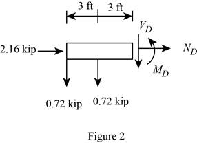
Mechanics of Materials (10th Edition), Chapter 1, Problem 1.1RP , additional homework tip  2

Refer to Figure 2.

Find the internal loadings as shown below.

Apply the Equations of Equilibrium as shown below.

Summation of forces along horizontal direction is Equal to zero.

Fx=0ND+2.16=0ND=2.16kip

Summation of forces along vertical direction is Equal to zero.

Fy=0VD+0.720.72=0VD=0

Take moment about D is Equal to zero.

MD=0MD0.72×3=0MD2.16=0MD=2.16kipft

Hence, the resultant internal loadings at cross section at D are ND=2.16kip,VD=0_, and MD=2.16kipft_.

Find the loading at the center of the column FC (PFC):

PFC=Weight of columnFC×LengthofcolumnFC

Substitute 180lb/ft for the weight of column FC and 16 ft for the length of column FC.

PFC=180×16=2,880lb

Convert the unit from lb to kip.

PFC=2,880lb×1kip1,000lb=2.88kip

Sketch the Free Body Diagram of the beam FC shown in Figure 3.
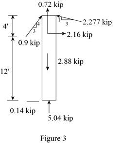
Mechanics of Materials (10th Edition), Chapter 1, Problem 1.1RP , additional homework tip  3

Refer to Figure 3.

Find the angle of cable CG to the horizontal.

sinθ=342+32sinθ=35θ=sin1(0.6)θ=36.87°

Find the tension in cable CG as shown below.

Summation of forces along horizontal direction is Equal to zero.

Fx=0FCGcos36.87°2.277sin18.43°=00.8FCG0.72=00.8FCG=0.72

FCG=0.9kip

Find the loading at the center of the column FE (PFE):

PFE=Weight of columnFE×LengthofcolumnFE

Substitute 180lb/ft for the weight of column FE and 4 ft for the length of column FC.

PFE=180×4=720lb

Convert the unit from lb to kip.

PFE=720lb×1kip1,000lb=0.72kip

Sketch the Free Body Diagram of the section for point E as shown in Figure 4.
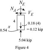
Mechanics of Materials (10th Edition), Chapter 1, Problem 1.1RP , additional homework tip  4

Refer to Figure 4.

Find the internal loadings as shown below.

Apply the Equations of Equilibrium as shown below.

Summation of forces along horizontal direction is Equal to zero.

Fx=0VE0.54=0VE=0.54kip

Summation of forces along vertical direction is Equal to zero.

Fy=0NE+0.725.04=0NE4.32=0NE=4.32kip

Take moment about E is Equal to zero.

ME=0ME+0.54×4=0ME+2.16=0ME=2.16kipft

Therefore, the resultant internal loadings at cross section at E are NE=4.32kip,VE=0.54kip_, and ME=2.16kipft_.

Want to see more full solutions like this?

Subscribe now to access step-by-step solutions to millions of textbook problems written by subject matter experts!
11:16
Students have asked these similar questions
The boom DF of the jib crane and the column DE have a uniform weight of 50 lb>ft. If the supported load is 300 lb, determine the resultant internal loadings in the crane on cross-sections at points A, B, and C.
The hand crank that is used in a press has the dimensions shown. Determine the resultant internal loadings acting on the cross-section at point A if a vertical force of 50 lb is applied to the handle as shown. Assume thecrank is fixed to the shaft at B.
Determine the loads acting on pins A and D of the frame shown. On the other hand, if the pin at B can withstand a maximum shear force of 800 lb, determine the maximum distributed load that can be applied to member AB.

Chapter 1 Solutions

Mechanics of Materials (10th Edition)

Ch. 1.2 - The shaft is supported by a smooth thrust bearing...Ch. 1.2 - Determine the resultant internal loadings acting...Ch. 1.2 - Determine the resultant internal loadings on the...Ch. 1.2 - Determine the resultant internal loadings at cross...Ch. 1.2 - The beam supports the distributed load shown....Ch. 1.2 - The beam supports the distributed load shown....Ch. 1.2 - The boom DF of the jib crane and the column DE...Ch. 1.2 - Determine the resultant internal loadings acting...Ch. 1.2 - Determine the resultant internal loadings acting...Ch. 1.2 - The blade of the hacksaw is subjected to a...Ch. 1.2 - The blade of the hacksaw is subjected to a...Ch. 1.2 - The beam supports the triangular distributed load...Ch. 1.2 - The beam supports the distributed load shown....Ch. 1.2 - The shaft is supported at its ends by two bearings...Ch. 1.2 - The shaft is supported at its ends by two bearings...Ch. 1.2 - The hand crank that is used in a press has the...Ch. 1.2 - Determine the resultant internal loadings acting...Ch. 1.2 - Determine the resultant internal loadings acting...Ch. 1.2 - The metal stud punch is subjected to a force of...Ch. 1.2 - Determine the resultant internal loadings acting...Ch. 1.2 - Determine the resultant internal loadings acting...Ch. 1.2 - Determine the resultant internal loadings acting...Ch. 1.2 - Determine the resultant internal loadings acting...Ch. 1.2 - The pipe has a mass of 12 kg/m. If it is fixed to...Ch. 1.2 - If the drill bit jams when the brace is subjected...Ch. 1.2 - The curved rod AD of radius r has a weight per...Ch. 1.2 - A differential element taken from a curved bar is...Ch. 1.5 - In each case, determine the largest internal shear...Ch. 1.5 - Determine the largest internal normal force in the...Ch. 1.5 - Determine the internal normal force at section A...Ch. 1.5 - The lever is held to the fixed shaft using the pin...Ch. 1.5 - The single-V butt joint transmits the force of 5...Ch. 1.5 - The uniform beam is supported by two rods AB and...Ch. 1.5 - Determine the average normal stress on the cross...Ch. 1.5 - Determine the average normal stress on the cross...Ch. 1.5 - If the 600-kN force acts through the centroid of...Ch. 1.5 - Determine the average normal stress at points A,...Ch. 1.5 - Determine the average normal stress in rod AB if...Ch. 1.5 - The supporting wheel on a scaffold is held in...Ch. 1.5 - Determine the largest intensity w of the uniform...Ch. 1.5 - The bar has a cross-sectional area A and is...Ch. 1.5 - The small block has a thickness of 0.5 in. If the...Ch. 1.5 - If the material fails when the average normal...Ch. 1.5 - If the block is subjected to a centrally applied...Ch. 1.5 - The plate has a width of 0.5 m. If the stress...Ch. 1.5 - The board is subjected to a tensile force of 200...Ch. 1.5 - The boom has a uniform weight of 600 lb and is...Ch. 1.5 - Determine the average normal stress in each of the...Ch. 1.5 - If the average normal stress in each of the...Ch. 1.5 - Determine the maximum average shear stress in pin...Ch. 1.5 - If P=5 kN, determine the average shear stress in...Ch. 1.5 - Determine the maximum magnitude P of the loads the...Ch. 1.5 - The column is made of concrete having a density of...Ch. 1.5 - The beam is supported by two rods AB and CD that...Ch. 1.5 - The beam is supported by two rods AB and CD that...Ch. 1.5 - If P = 15 kN, determine the average shear stress...Ch. 1.5 - The railcar docklight is supported by the...Ch. 1.5 - The plastic block is subjected to an axial...Ch. 1.5 - The two steel members are joined together using a...Ch. 1.5 - The bar has a cross-sectional area of 400(106) m2....Ch. 1.5 - The bar has a cross-sectional area of 400(106) m2....Ch. 1.5 - The two members used in the construction of an...Ch. 1.5 - The 2-Mg concrete pipe has a center of mass at...Ch. 1.5 - The 2-Mg concrete pipe has a center of mass at...Ch. 1.5 - The pier is made of material having a specific...Ch. 1.5 - Rods AB and BC have diameters of 4 mm and 6 mm,...Ch. 1.5 - The uniform bar, having a cross-sectional area of...Ch. 1.5 - The bar has a cross-sectional area of 400(106) m2....Ch. 1.5 - The bar has a cross-sectional area of 400(106) m2....Ch. 1.5 - The prismatic bar has a cross-sectional area A. If...Ch. 1.5 - The prismatic bar has a cross-sectional area A. If...Ch. 1.5 - The bars of the truss each have a cross-sectional...Ch. 1.5 - The bars of the truss each have a cross-sectional...Ch. 1.5 - Determine the largest load P that can be applied...Ch. 1.5 - Determine the greatest constant angular velocity ...Ch. 1.5 - The radius of the pedestal is defined by r =...Ch. 1.7 - Rods AC and BC are used to suspend the 200-kg...Ch. 1.7 - If it is subjected to double shear, determine the...Ch. 1.7 - Determine the maximum average shear stress...Ch. 1.7 - If each of the three nails has a diameter of 4 mm...Ch. 1.7 - The strut is glued to the horizontal member at...Ch. 1.7 - Determine the maximum average shear stress...Ch. 1.7 - If the eyebolt is made of a material having a...Ch. 1.7 - If the bar assembly is made of a material having a...Ch. 1.7 - Determine the maximum force P that can be applied...Ch. 1.7 - The pin is made of a material having a failure...Ch. 1.7 - If the bolt head and the supporting bracket are...Ch. 1.7 - Six nails are used to hold the hanger at A against...Ch. 1.7 - If A and B are both made of wood and are 38 in....Ch. 1.7 - Prob. 1.70PCh. 1.7 - The connection is made using a bolt and nut and...Ch. 1.7 - The tension member is fastened together using two...Ch. 1.7 - The steel swivel bushing in the elevator control...Ch. 1.7 - The spring mechanism is used as a shock absorber...Ch. 1.7 - Determine the size of square bearing plates A and...Ch. 1.7 - Determine the maximum load P that can be applied...Ch. 1.7 - Determine the required diameter of the pins at A...Ch. 1.7 - If the allowable tensile stress for wires AB and...Ch. 1.7 - If the allowable tensile stress for wires AB and...Ch. 1.7 - The cotter is used to hold the two rods together....Ch. 1.7 - Determine the required diameter of the pins at A...Ch. 1.7 - The steel pipe is supported on the circular base...Ch. 1.7 - The boom is supported by the winch cable that has...Ch. 1.7 - The boom is supported by the winch cable that has...Ch. 1.7 - The assembly consists of three disks A, B, and C...Ch. 1.7 - The two aluminum rods support the vertical force...Ch. 1.7 - The two aluminum rods AB and AC have diameters of...Ch. 1.7 - Determine the required minimum thickness t of...Ch. 1.7 - Determine the maximum allowable load P that can be...Ch. 1.7 - The compound wooden beam is connected together by...Ch. 1.7 - The hanger is supported using the rectangular pin....Ch. 1.7 - The hanger is supported using the rectangular pin....Ch. 1.7 - The rods AB and CD are made of steel. Determine...Ch. 1.7 - The aluminum bracket A is used to support the...Ch. 1.7 - If the allowable tensile stress for the bar is...Ch. 1.7 - The bar is connected to the support using a pin...Ch. 1 - The beam AB is pin supported at A and supported by...Ch. 1 - The long bolt passes through the 30-mm-thick...Ch. 1 - Determine the required thickness of member BC to...Ch. 1 - The circular punch B exerts a force of 2 kN on the...Ch. 1 - Determine the average punching shear stress the...Ch. 1 - The 150 mm by 150 mm block of aluminum supports a...Ch. 1 - The yoke-and-rod connection is subjected to a...Ch. 1 - The cable has a specific weight (weight/volume)...

Additional Engineering Textbook Solutions

Find more solutions based on key concepts
What parts are included in the vehicle chassis?

Automotive Technology: Principles, Diagnosis, And Service (6th Edition) (halderman Automotive Series)

The horizontal and the vertical components of force at the pins A and D.

Engineering Mechanics: Statics & Dynamics (14th Edition)

Knowledge Booster
Background pattern image
Mechanical Engineering
Learn more about
Need a deep-dive on the concept behind this application? Look no further. Learn more about this topic, mechanical-engineering and related others by exploring similar questions and additional content below.
Similar questions
SEE MORE QUESTIONS
Recommended textbooks for you
Text book image
International Edition---engineering Mechanics: St...
Mechanical Engineering
ISBN:9781305501607
Author:Andrew Pytel And Jaan Kiusalaas
Publisher:CENGAGE L
Column buckling; Author: Amber Book;https://www.youtube.com/watch?v=AvvaCi_Nn94;License: Standard Youtube License