
Concept explainers
Videos
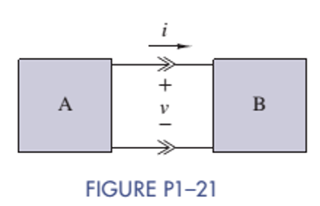
Two electrical devices are connected as shown in Figure P1-21. Using the reference marks shown in the figure, find the power transferred and state whether the power is transferred from A to B or B to A when
(a)
(b)
(c)
(d)
Want to see the full answer?
Check out a sample textbook solution
Chapter 1 Solutions
ANALYSIS+DESIGN OF LINEAR CIRCUITS(LL)
Additional Engineering Textbook Solutions
Introductory Circuit Analysis (13th Edition)
Electric Circuits (10th Edition)
Fundamentals of Applied Electromagnetics (7th Edition)
Electric Circuits. (11th Edition)
Basic Engineering Circuit Analysis
Electrical Engineering: Principles & Applications (7th Edition)


- Consider the circuit shown in Figure P1.64. Use Ohm’s law, KVL, and KCL to find V x.arrow_forwardFind the equivalent resistance between the points A and B for the circuit shown in figure1. Draw the equivalent circuit during every simplification step.arrow_forwardThe circuit element shown in Figure P1.9 has v = 12 V and i ba = -2A. What is the value of v baBe sure to give the correct algebraic sign. What is the value of i? Is energy delivered tothe element or taken from it?arrow_forward
- A combination of three resistors R1, R2, and R3 in series is connected across a voltage source VT. The voltage drop across R1 and R3 are 10 V and 36 V, respectively. If the current supplied by the source voltage is 1.4 A and the total power supplied by the source is 70 W, calculate the equivalent resistance (in ohms) across the voltage source. NOTE Express your final answers accurate to four decimal places; avoid rounding off intermediate values in the solutions to avoid deviation due to rounding-off within the solution. USE ENG NOTATIONarrow_forwardConsider the circuit shown in Figure P1.36. a. Which elements are in parallel? b. What is the relationship between v a and v b ? c. Given that v a = 2 V and v d = -5 V determine the values of v b and v c.arrow_forwardslove the value of i1,i2andi3 in the circuit of figure Q2a A=2arrow_forward
- Use KVL to solve for the voltages v a, v b and v c in Figure P1.42arrow_forwardconsider the circuit shown in (Figure 1). Suppose that i = 1.6 AA. Find the value of v1 and i2. Express your answer to three significant figures and include the appropriate units.arrow_forwardWhat is the voltage of UR1 falling on the resistor R1 in the circuit given in the figure?arrow_forward
- Since R1=3198.15ohm, R2=9694.26ohm and Ri=Infinite in the circuit given in the figure, write the equivalent resistance in Ohms between the terminals A-B. When making your transactions, 2 digits will be taken after the dot. Write the result you found according to the margin of error of ± 10% (plus/minus ten percent). While writing the answer, a space is written in front of the value (kOhm, ohm, V, A) etc. values should not be written. Only numeric values should be entered. A period (.) must be used as a decimal separator. Do not use thousands separators (do not use signs such as semicolons). An example notation is given below. Let the value you find be 1.15Kohm. You should write 1150.00 in the box. Let the value you find be 432.63 ohms. You should write 432.63 in the box. If the correct answer is X, values entered in the range of X ± (X*10/100) (including limits) will be accepted. If x=50, it will be accepted as between [45,55].arrow_forwardsubject:Circuits 1please this one too give me a slightly favor can you answer this questions please wanna learn more im having difficuilty about this questionsarrow_forwardA is measured in coulombs, B is measured in seconds, C is measured in volts, and D is measured in seconds. Give the power of this component at t2 = 7 sec. You must round your answer to the nearest thousandth and give your answer as an integer followed by the appropriate metric prefix and the letter that represents the units of power.arrow_forward
 Introductory Circuit Analysis (13th Edition)Electrical EngineeringISBN:9780133923605Author:Robert L. BoylestadPublisher:PEARSON
 Delmar's Standard Textbook Of ElectricityElectrical EngineeringISBN:9781337900348Author:Stephen L. HermanPublisher:Cengage Learning
 Programmable Logic ControllersElectrical EngineeringISBN:9780073373843Author:Frank D. PetruzellaPublisher:McGraw-Hill Education
 Fundamentals of Electric CircuitsElectrical EngineeringISBN:9780078028229Author:Charles K Alexander, Matthew SadikuPublisher:McGraw-Hill Education
 Electric Circuits. (11th Edition)Electrical EngineeringISBN:9780134746968Author:James W. Nilsson, Susan RiedelPublisher:PEARSON
 Engineering ElectromagneticsElectrical EngineeringISBN:9780078028151Author:Hayt, William H. (william Hart), Jr, BUCK, John A.Publisher:Mcgraw-hill Education,