
Concept explainers
Videos
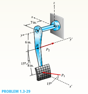
A special vehicle brake is clamped at O when the brake force P1 is applied (see figure). Force P1= 50 lb and lies in a plane that is parallel to the x-z plane and is applied at C normal to line BC. Force P2= 40 lb and is applied al B in the -y direction.
(a) Find reactions at support O.
(b) Find internal stress resultants N, V, T. and M at
the mid-point of segment OA.
(a)
Reactions at support O.
Answer to Problem 1.3.29P
The correct answers are:
Explanation of Solution
Given Information:
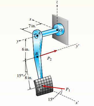
You have following figure with all relevant information:

and
Draw free body diagram of joints and use equilibrium of forces to determine the unknown facts.
Calculation:
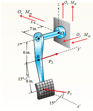
Draw free body diagram as shown in the following figure:

The forces and corresponding position vectors are:
| Force | Position vector |
Take equilibrium of forces vector from:
The vector equation yields three equations in components form as below:
Put
Now take equilibrium of moments about O in vector form as:
Put
Conclusion:
Therefore the forces are:
(b)
Internal stress resultants N,V,T, and M at the mid pint of segment OA.
Answer to Problem 1.3.29P
The correct answers are:
Explanation of Solution
Given Information:
You have following figure with all relevant information,
and
Draw free body diagram of joints and use equilibrium of forces to determine the unknowns.
Calculation:
Draw free body diagram as shown in the following figure,
The forces and corresponding position vectors are:
| Force | Position vector |
Take equilibrium of forces vector form:
The vector equation yields three equations in components form as below:
Put
Now take equilibrium of moments about O in vector form as:
Put
Calculation of internal resultants:
Consider the following free body diagram,
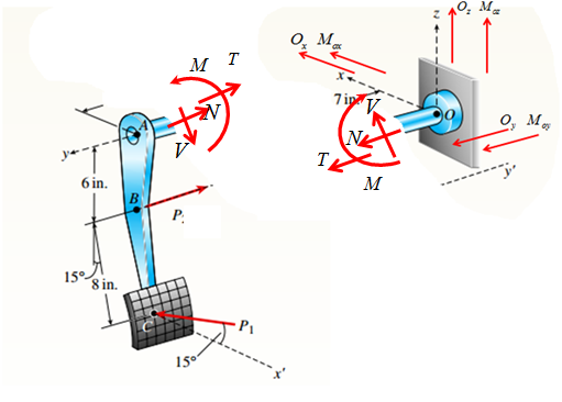
Analyze the right hand side of the free body diagram in the above figure.
Take equilibrium of torques in y-direction as,
Take equilibrium of forces in y-direction as,
Take equilibrium of forces in xz-plane as:
Calculate bending moment as:
Conclusion:
Therefore the internal stress resultants are:
Want to see more full solutions like this?
Chapter 1 Solutions
Mechanics of Materials (MindTap Course List)


- A mountain bike is moving along a flat path at constant velocity. At some instant, the rider (weight = 670 N) applies pedal and hand forces, as shown in the figure part a. (a) Find reaction forces at the front and rear hubs. (Assume that the bike is pin supported at the rear hub and roller supported at the front hub.) (b) Find internal stress resultants N, V, and M in the inclined seat post (see figure part barrow_forwardA plane frame with a pin support at A and roller supports at C and £ has a cable attached at E. which runs over Frictionless pulleys al D and B (see figure). The cable force is known to be 400 N. There is a pin connection just Lo the left of joint C. (a) Find reactions at supports^, C, and E. (b) Find internal stress, resultants N, V, and M just to the right of joint C. (c) Find resultant force in the pin near C.arrow_forwardA bar ABC revolves in a horizontal plane about a vertical axis at the midpoint C (see figure). The bar, which has a length 2L and crass-sectional area A, revolves at constant angular speed at. Each half of the bar (AC and BC) has a weight W, and supports a weight W2at its end. Derive the following formula for the elongation of one-half of the bar (that is. the elongation of either AC ar BC). =L223gEA(w1+3w2) in which E is t he modulus of elasticity of the material of the bar and g is the acceleration of gravity.arrow_forward
- A hollow circular pipe (see figure} support s a load P that is uniformly distributed around a cap plate at the top of the lower pipe. The inner and outer diameters of the upper and lower parts of the pipe are d1= 50 mm, d2= 60 mm, rf3 = 57 mm, and d1= 64 mm, respectively. Pipe lengths are Lt= 2 m and L, = 3 m. Neglect the self-weight of the pipes. Assume that cap plate thickness is small compared to I, and E,. Let E = 110 MPa. (a) If the tensile stress in the upper part is d = 10.5 MPa. what is load PI Also, what are reactions ft, at the upper support and R-, at the lower support? What is the stress ar(MPa) in the lower part? (b) Find displacement S(mm) at the cap plate. Plot the axial force diagram (AFD) [Ar(.f)] and axial displacement diagram (ADD)[5(.t)]. (c) Add the uniformly distributed load q along the censorial axis of pipe segment 2. Find q (kN/m) so that It, = 0. Assume that load P from part (a) is also applied.arrow_forwardA cylindrical pressure vessel having a radius r = 14 in. and wall thickness t = 0,5 in, is subjected to internal pressure p = 375 psi, In addition, a torque T = 90 kip-ft acts at each end of the cylinder (see figure), (a) Determine the maximum tensile stress ctniXand the maximum in-plane shear stress Tmjv in the wall of the cylinder. (b) If the allowable in-plane shear stress is 4.5 ksi, what is the maximum allowable torque T\ (c) If 7 = 150 kip-ft and allowable in-plane shear and allowable normal stresses are 4.5 ksi and 11.5 ksi, respectively, what is the minimum required wall thicknessarrow_forwardA plane frame is restrained al joints A and C, as shown in the figure. Members AB and BC are pin connected at B. A triangularly distributed lateral load with a peak intensity or 90 lb/ft acts on AB. A concentrated moment is applied at joint C. (a) Find reactions at supports A and C. (b) Find internal stress resultants A', V, and \f at x = 3 ft on column AB.arrow_forward
- A plane Frame with pin supports at A and E has a cable attached at C, which runs over a friction-less pulley at F(see figure). The cable Force is known to be 500 lb. (a) Find reactions at supports A and E. (b) Find internal stress resultants N, V, and M at point H.arrow_forward1.3-15 A space truss is restrained at joints A, B, and C, as shown in the figure. Load 2P is applied at in the -x direction at joint A, load 3P acts in the + - direction at joint B. and load P is applied in the + r direction al joint C. Coordinates of all joints are given in terms of dimension variable L (see figure). (a) Find reaction force components Ayand Azin terms of load variable P. (b) Find the axial force in truss member AB in terms of load variable P.arrow_forwardA single steel strut AB with a diameter (a) Find the strut force Fs and average normal stress ds= 8 mm supports the vehicle engine hood of a in the strut. mass 20 kg that pivots about hinges at C and D (see (b) Find the average shear stress t aver in the bolt at A,figure parts a and b). The strut is bent into a loop at (C) Find the average bearing stress bon the bolt at A. its end and then attached to a bolt at A with a diameter db= 10 mm. Strut AB lies in a vertical plane.arrow_forward
- A vertical pole of solid, circular cross section is twisted by horizontal forces P = 5kN acting at the ends of a rigid horizontal arm AB (see figure part a). The distance from the outside of the pole to the line of action of each force is c = 125 mm (sec figure part b) and the pole height L = 350 mm. (a) If the allowable shear stress in the pole is 30 MPa, what is the minimum required diameter dminof the pole? (b) What is the torsional stiffness of the pole (kN · m/rad)? Assume that G = 28 GPa. (c) If two translation al springs, each with stiffness k =2550 kN/m, are added at 2c/5 from A and B (see figure part c), repeat part (a) to find dmin. Hint: Consider the pole and pair of springs as "springs in parallel."arrow_forwardA soccer goal is subjected to gravity loads (in the - z direction, w = 73 N/m for DG, BG, and BC; w = 29 N/m for all other members; see figure) and a force F = 200 N applied eccentrically at the mid-height of member DG. Find reactions at sup ports C, D, and H.arrow_forwardA round bar ABC of length 2L (see figure) rotates about an axis through the midpoint C with constant angular speed w (radians per second). The material of the bar has weight density y. (a) Derive a formula for the tensile stress a’ in the bar as a function of the distance x from the midpoint C. (b) What is the maximum tensile stress a max?arrow_forward
 Mechanics of Materials (MindTap Course List)Mechanical EngineeringISBN:9781337093347Author:Barry J. Goodno, James M. GerePublisher:Cengage Learning