
Concept explainers
Videos
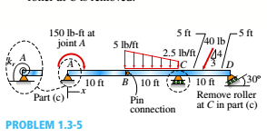
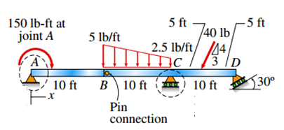
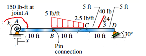
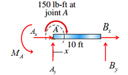
Segments AB and BCD of beam ABCD are pin connected at x = 10 ft. The beam is supported by a pin support at A and roller supports at C and D; the roller at D is rotated by 30* from the x axis (see figure). A trapezoidal distributed load on BC varies in intensity from 5 lb/ft at B to 2.5 lb/ft at C. A concentrated moment is applied at joint A, and a 40-lb inclined load is applied at the mid-span or CD.
(a) Find reactions at supports A, C, and D.
(b) Find the resultant force in the pin connection at B.
(c) Repeat parts (a) and (b) if a rotational spring(kr= 50 ft-lb/radian ) is added at A and the roller at C is removed.
(a)
Determine the reactions at supports A, C, and D in the following figure.

Answer to Problem 1.3.5P
The correct answers are:
Explanation of Solution
Given Information:
The following figure is given for reference.
Calculation:
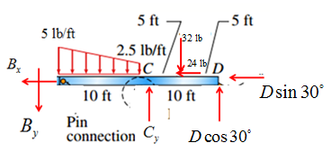
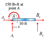
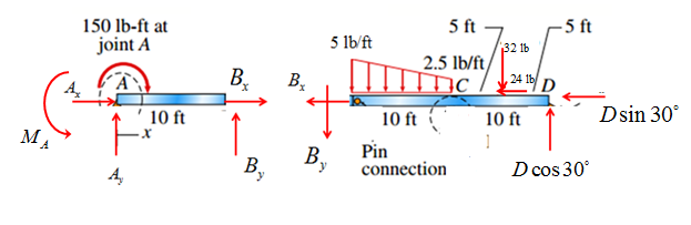
To find support reactions, draw free body diagram as shown below.

First analyze left hand side of the above figure as shown below.

Take equilibrium of moments about point A,
Take equilibrium of forces in
Take equilibrium of forces in
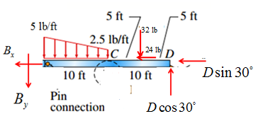
Now, analyze the right hand side of the above figure as shown below,
Take equilibrium of moments about point B,
Take equilibrium of forces in
Solve equations and for
Take equilibrium of forces in
Now solve equation
Conclusion:
Thus reactions forces are:
(b)
Determine the resultant force in pin B.

Answer to Problem 1.3.5P
The correct answer is:
Explanation of Solution
Given Information:
The following figure is given for reference.

Calculation:
To find support reactions, draw free body diagram as shown below.
First analyze left hand side of the above figure as shown below.
Take equilibrium of moments about point A,
Take equilibrium of forces in
Now, analyze the right hand side of the above figure as shown below,

Take equilibrium of moments about point B,
Take equilibrium of forces in
Solve equations and for
Take equilibrium of forces in
Conclusion:
Thus resultant force is:
(c)
Determine the reactions at supports A, C, and D; and resultant force at B in the following figure.
Answer to Problem 1.3.5P
The correct answers are:
Explanation of Solution
Given Information:
The following figure is given for reference.

Calculation:
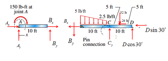
To find support reactions, draw free body diagram as shown below.
First, analyze the right hand side of the above figure as shown below,
Take equilibrium of moments about point B,
So
Take equilibrium of forces in
Take equilibrium of forces in
Thus resultant force at B is:
Now, analyze left hand side of the above figure as shown below.
Take equilibrium of moments about point A,
Take equilibrium of forces in
Take equilibrium of forces in
Conclusion:
The correct answers are:
Want to see more full solutions like this?
Chapter 1 Solutions
Mechanics of Materials (MindTap Course List)


- Beam A BCD has a sliding support at A, roller supports at C and A and a pin connection at B (see figure). Assume that the beam has a rectangular cross section (b = 4 in., h = 12 in.). Uniform load q acts on ABC and a concentrated moment is applied at D. Let load variable q = 1750 lb/ft, and assume that dimension variable L = 4 ft. First, use statics to confirm the reaction moment at A and the reaction forces at Cand A as given in the figure. Then find the ratio of the magnitudes of the principal stresses (crj/os) just left of support Cat a distance d = 8 in. up from the bottom,arrow_forwardBeam A BCD has a sliding support at A, roller supports at C and A and a pin connection at B (see figure). Assume that the beam has a rectangular cross section (b = 4 in., h = 12 in.). Uniform load q acts on ABC and a concentrated moment is applied at D. Let load variable q = 1750 lb/ft, and assume that dimension variable L = 4 ft. First, use statics to confirm the reaction moment at A and the reaction forces at C and A as given in the figure. Then find the ratio of the magnitudes of the principal stresses (crj/os) just left of support Cat a distance d = 8 in. up from the bottom, The pedal and crank are in a horizontal plane and points A and B are located on the top of the crank. The load P = 160 lb acts in the vertical direction and the distances (in the horizontal plane) between the line of action of the load and points A and B are b\ = 5.0 in., h-, = 2.5 in., and/>3 = 1.0 in. Assume that the crank has a solid circular cross section with diameter d = 0.6 inarrow_forwardA cantilever beam of W 12 × 14 section and length L = 9 ft supports a slightly inclined load P = 500 lb at the free end (see figure). Plot a graph of the stress o 4at point A as a function of the angle of inclination or Plot a graph of the angle L/3, which locates the neutral axis ma as a function of the angle a. (When plotting the graphs, let a vary from 0 to 10º) See Table F-1(a) of Appendix F for the dimensions and properties of the beam.arrow_forward
- A beam with a guided support and 10-ft span supports a distributed load of intensity q = 660 lb/ft over its first half (see figure part a) and a moment Mq = 300 ft-lb at joint B. The beam consists of a wood member (nominal dimensions 6 in. x 12 in. and actual dimensions 5.5 in. x 11.5 in. in cross section, as shown in the figure part b) that is reinforced by 0.25-in.-thick steel plates on top and bottom. The moduli of elasticity for the steel and wood are £s = 30 X 106 psi and £"w = 1.5 X 10⁶ psi, respectively. Calculate the maximum bending stresses trs in the steel plates and rw in the wood member due to the applied loads. If the allowable bending stress in the steel plates is = 14,000 psi and that in the wood is (T.dV!= 900 psi, find qmiiX. (Assume that the moment at .fi, A/0, remains at 300 ft-lb.) If q = 660 lb/ft and allowable stress values in part (b) apply, what is Müm^ at B?arrow_forwardUniform load q = 10 lb/ft acts over part of the span of fixed-end beam AB (see figure). Upward load P = 250 lb is applied 9 ft to the right of joint A. Find the reactions at A and B.arrow_forwardSolve the preceding problem for a cantilever beam with data as b = 4 in., h = 9 in., L = 10 ft, P = 325 lb, and x = 45°.arrow_forward
- A foot bridge on a hiking trail is constructed using two timber logs each having a diameter d = 0.5 m (see figure a). The bridge is simply supported and has a length L = 4 m. The top of each log is trimmed to form the walking surface (see Fig, b)LA simplified model of the bridge is shown in Fig. g. Each log must carry its own weight w = 1.2 kN/m and the weight (P = 850 N) of a person at mid-span, (see Fig. b). Determine the maximum tensile and compressive stresses in the beam (Fig, b) due to bending. If load h is unchanged, find the maximum permissible value of load ... if the allowable normal stress in tension and compression is 2.5 M Pa.arrow_forwardBeam ABC is fixed at support A and rests (at point B) upon the midpoint of beam DE (see part a of the figure). Thus, beam, ABC may be represented as a propped cantilever beam with an overhang BC and a linearly elastic support of stiffness k at point B (see part b of the figure). The distance from A to B is L = 10 ft, the distance from B to C is L/2 = 5 ft, and the length of beam DE is L = 10 ft. Both beams have the same flexural rigidity EI. A concentrated load P = 1700 lb acts at t lie free end of beam ABC. Determine the reactions RA, RB+ and MAfor beam ABC. Also, draw the shear-force and bending-moment diagrams for beam ABC, labeling all critical ordinates.arrow_forwardTwo pipe columns (AB, FC) are pin-connected to a rigid beam (BCD), as shown in the figure. Each pipe column has a modulus of E, but heights (L1or L2) and outer diameters (d1or different for each column. Assume the inner diameter of each column is 3/4 of outer diameter. Uniformly distributed downward load q = 2PIL is applied over a distance of 3L/4 along BC, and concentrated load PIA is applied downward at D. (a) Derive a formula for the displacementarrow_forward
- The cantilever beam AB shown in the figure is an S6 × 12.5 steel I-beam with E = 30 × 106 psi. The simple beam DE is a wood beam 4 in. x 12 in. (nominal dimensions) in cross section with E = 1.5 x 10⁶ psi. A steel rod AC of diameter 0.25 in., length 10 ft, and E = 30 x 106 psi serves as a hanger joining the two beams. The hanger fits snugly between the beams before the uniform load is applied to beam DE. Determine the tensile force Fin the hanger and the maximum bending moments MABand MDEin the two beams due to the uniform load, which has an intensity q = 400 lb/ft. Hint: To aid in obtaining the maximum bending moment in beam DE, draw the shear-force and bending-moment diagrams.arrow_forwardFrame ABCD carries two concentrated loads (2P at T and P at ZX see figure) and also a linearly varying distributed load on AB, Find expressions for shear force Fand moment A/at x = L/3 of beam AB in terms of peak load intensity q0, force P, and beam length variable L. Let q0= P/L.arrow_forwardA horizontal beam AB is pin-supported at end A and carries a clockwise moment M at joint B, as shown in the figure. The beam is also supported at C by a pinned-end column of length L: the column is restrained laterally at 0.6Z, from the base at D. Assume the column can only buckle in the plane of the frame. The column is a solid steel bar (E = 200 GPa) of square cross section having length L = 2.4 m and side dimensions h = 70 mm. Let dimensions d = LI2. Based upon the critical load of the column, determine the allowable moment M if the factor of safety with respect to buckling is n = 2.0.arrow_forward
 Mechanics of Materials (MindTap Course List)Mechanical EngineeringISBN:9781337093347Author:Barry J. Goodno, James M. GerePublisher:Cengage Learning