
Concept explainers
Videos
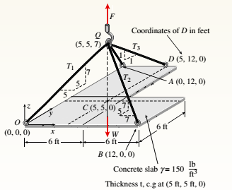
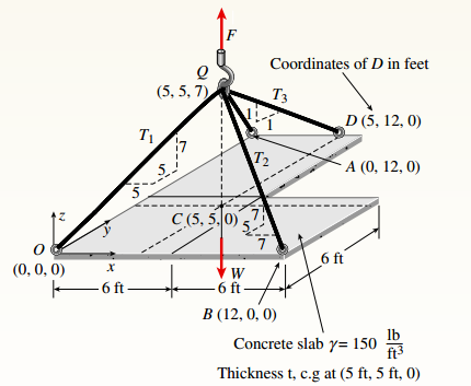
An L-shaped reinforced concrete slab 12 Ft X 12 ft, with a 6 Ft X 6 ft cut-out and thickness t = 9.0 in, is lifted by three cables attached at O, B, and D, as shown in the figure. The cables are are combined at point Q, which is 7.0 Ft above the top of the slab and directly above the center of mass at C. Each cable has an effective cross-sectional area of Ae= 0.12 in2.
(a) Find the tensile force Tr(i = 1, 2, 3) in each cable due to the weight W of the concrete slab
(ignore weight of cables).
(b) Find the average stress ov in each cable. (See Table I-1 in Appendix I for the weight density of reinforced concrete.)
(c) Add cable AQ so that OQA is one continuous cable, with each segment having Force T, which is connected to cables BQ and DQ at point Q. Repeat parts (a) and (b). Hini: There are now three Forced equilibrium equations and one constrain equation, T1= T4.
(a)
Tensile force T in each cable due to weight.
Answer to Problem 1.4.13P
Tensile force T is:
Explanation of Solution
Given Information:
You have the following figure with all relevant information:

Thickness (t) is 9 in.
Calculation:
Consider the free body diagram as:
To calculate external reaction force F, take equilibrium of forces as:
The following force acts on point Q:
Take equilibrium of forces at Q as:
Solve the above equation to get:
Conclusion:
Therefore, the correct answers are
(b)
Average stress in each cable.
Answer to Problem 1.4.13P
Stress in each cable is
Explanation of Solution
Given Information:
You have following figure with all relevant information:

Thickness (t) is 9 in. and cross-sectional area of each cable is
Calculation:
Consider the free body diagram as,

To calculate external reaction force F, take equilibrium of forces as,
The following forces acts on point Q:
Take equilibrium of forces at Q as:
Solve the above equation to get,
Calculate stress as,
Conclusion:
Therefore, the correct answer is:
(c)
Tensile force and average stress in each cable.
Answer to Problem 1.4.13P
Stress in each cable is:
Explanation of Solution
Given Information:
You have following figure with all relevant information:

Thickness (t) is 9 in. and cross-sectional area of each cable is
Calculation:
Consider the free body diagram as,

To calculate external reaction force F, take equilibrium of forces as:
The following force acts on point Q:
Take equilibrium of force at Q as:
Solve the above equation along with
Calculate stress as:
Conclusion:
Therefore, the correct answers are:
Want to see more full solutions like this?
Chapter 1 Solutions
Mechanics of Materials (MindTap Course List)


- Two pipe columns (AB, FC) are pin-connected to a rigid beam (BCD), as shown in the figure. Each pipe column has a modulus of E, but heights (L1or L2) and outer diameters (d1or different for each column. Assume the inner diameter of each column is 3/4 of outer diameter. Uniformly distributed downward load q = 2PIL is applied over a distance of 3L/4 along BC, and concentrated load PIA is applied downward at D. (a) Derive a formula for the displacementarrow_forwardA large precast concrete panel for a warehouse is raised using two sets of cables at two lift lines, as shown in the figure part a. Cable 1 has a length L1 = 22 Ft, cable 2 has a length L2= 10 ft, and the distance along the panel between lift points Band D is d = 14 ft (see figure part b). The total weight of the panel is W = 85 kips. Assuming the cable lift Forces F at each lift line are about equal, use the simplified model of one half of the panel in figure part b to perform your analysis for the lift position shown. Find the required cross-sectional area AC of the cable if its breaking stress is 91 ksi and a factor of safety of 4 with respect to failure is desired.arrow_forwardThe roof over a concourse at an airport is supported by the use of pretensioned cables. At a typical joint in the roof structure, a strut AB is compressed by the action of tensile forces Fin a cable that makes an angle = 75° with the strut (see figure and photo). The strut is a circular tube of steel (E = 30,000 ksi) with outer diameter d2= 2.5 in. and inner diameter d1= 2.0 in. The strut is 5.75 ft long and is assumed to be pin-connected at both ends. Using a factor of safety n = 2.5 with respect to the critical load, determine the allowable force F in the cable.arrow_forward
- A cylindrical brick chimney of height H weighs w = 825 lb/ft of height (see figure). The inner and outer diameters are d1= 3 ft and d2= 4 ft, respectively. The wind pressure against the side of the chimney is p = 10 lb/ft2 of projected area. Determine the maximum height H if there is to be no tension in the brickwork.arrow_forwardA sign for an automobile service station is supported by two aluminum poles of hollow circular cross section, as shown in the figure. The poles are being designed to resist a wind pressure of 75 lb/ft" against the full area of the sign. The dimensions of the poles and sign are hx= 20 ft, /r =5 ft, and h = 10 ft. To prevent buckling of the walls of the poles, the thickness e is specified as one-tenth the outside diameter d. (a) Determine the minimum required diameter of the poles based upon an allowable bending stress of 7500 psi in the aluminum. (b) Determine the minimum required diameter based upon an allowable shear stress of 300 psi.arrow_forwardA retaining wall 6 ft high is constructed of horizontal wood planks 2.5 in. thick (actual dimension) that are supported by vertical wood piles of a 12 in, diameter (actual dimension), as shown in the figure. The lateral earth pressure is pt=125 lb/ft2 at the top of the wall and p2= 425 lb/ft2 at the bottom. Assuming that the allowable stress in the wood is 1175 psi, calculate the maximum permissible spacing s of the piles. Find the required diameter of the wood piles so that piles and planks (f = 2.5 in.) reach the allowable stress at the same time. Hint: Observe that the spacing of the piles may be governed by the load-carrying capacity of either the planks or the piles. Consider the piles to act as cantilever beams subjected to a trapezoidal distribution of load, and consider the planks to act as simple beams between the piles. To be on the safe side, assume that the pressure on the bottom plank is uniform and equal to the maximum pressure.arrow_forward
- The truss ABC shown in the figure supports a vertical load W at joint B. Each member is a slender circular steel pipe (E = 30,000 ksi) with an outside diameter of 4 in. and wall thickness 0.25 in. The distance between supports is 23 ft. Joint B is restrained against displacement perpendicular to the plane of the truss. Determine the critical value Wcr of the load.arrow_forwardThe L-shaped arm ABCD shown in the figure lies in a vertical plane and pivots about a horizontal pin at A. The arm has a constant cross-sectional area and total weight W. A vertical spring of stiffness k supports the arm at point B. (a) Obtain a formula for the elongation of the spring due to the weight of the arm. (b) Repeat part (a) if the pin support at A is moved to D.arrow_forwardA hollow circular tube T of a length L = 15 in. is uniformly compressed by a force P acting through a rigid plate (see figure). The outside and inside diameters of the tube are 3.0 and 2.75 in., respectively. A concentric solid circular bar B of 1.5 in. diameter is mounted inside the lube. When no load is present, there is a clearance c = 0.0I0 in. between the bar B and the rigid plate. Both bar and tube are made of steel having an c[autoplastic stress-strain diagram with E = 29 X LO3 ksi and err= 36 ksi. (a) Determine the yield load Pt- and the corresponding shortening 3yof the lube. (b) Determine the plastic load Ppand the corresponding shortening Spof the tube. (c) Construct a load-displacement diagram showing the load Pas ordinate and the shortening 5 of the tube as abscissa. Hint: The load-displacement diagram is not a single straight line in the region 0 ^ P ^ Prarrow_forward
- A square steel tube of a length L = 20 ft and width b2= 10.0 in. is hoisted by a crane (see figure). The lube hangs from a pin of diameter d that is held by the cables at points A and B. The cross section is a hollow square with an inner dimension b1= 8.5 in. and outer dimension b2= 10,0 in. The allowable shear stress in the pin is 8,700 psi. and the allowable bearing stress between the pin and the tube is 13,000 psi. Determine the minimum diameter of the pin in order to support the weight of the tube. Note: Disregard the rounded corners of the tube when calculating its weight.arrow_forwardA hollow circular pipe (see figure} support s a load P that is uniformly distributed around a cap plate at the top of the lower pipe. The inner and outer diameters of the upper and lower parts of the pipe are d1= 50 mm, d2= 60 mm, rf3 = 57 mm, and d1= 64 mm, respectively. Pipe lengths are Lt= 2 m and L, = 3 m. Neglect the self-weight of the pipes. Assume that cap plate thickness is small compared to I, and E,. Let E = 110 MPa. (a) If the tensile stress in the upper part is d = 10.5 MPa. what is load PI Also, what are reactions ft, at the upper support and R-, at the lower support? What is the stress ar(MPa) in the lower part? (b) Find displacement S(mm) at the cap plate. Plot the axial force diagram (AFD) [Ar(.f)] and axial displacement diagram (ADD)[5(.t)]. (c) Add the uniformly distributed load q along the censorial axis of pipe segment 2. Find q (kN/m) so that It, = 0. Assume that load P from part (a) is also applied.arrow_forwardSolve the preceding problem for a steel pipe column (E = 210 GPa) with length L = 1.2 m, inner diameter d2= 36 mm, and outer diameter d2=40 mm.arrow_forward
 Mechanics of Materials (MindTap Course List)Mechanical EngineeringISBN:9781337093347Author:Barry J. Goodno, James M. GerePublisher:Cengage Learning