
Electrical Engineering: Principles & Applications, Student Value Edition Plus Mastering Engineering with Pearson eText -- Access Card Package (7th Edition)
7th Edition
ISBN: 9780134702193
Author: Allan R. Hambley
Publisher: PEARSON
expand_more
expand_more
format_list_bulleted
Concept explainers
Videos
Textbook Question
Chapter 1, Problem 1.63P
Consider the circuit shown in Figure P1.63. Find the current
flowing through the resistor. Find the power for each element in the circuit. Which elements are receiving power?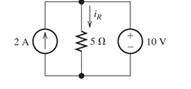
Figure P1. 63
Expert Solution & Answer

Learn your wayIncludes step-by-step video

schedule05:08
Students have asked these similar questions
Given:Vb = 100 voltsR = 10000 ohmsC = 200 μFAssuming that after a long period of time, the switch is flipped from position "A" to position "B" at t=0.
Determine the power dissipated by the resistor after t=1 sec.
Given:Vb = 100 voltsR = 10000 ohmsC = 200 μFAssuming that after a long period of time, the switch is flipped from position "A" to position "B" at t=0.
Determine the current in the source-free circuit after 1 second.
What is the composition of Biogas? List the Applications of Biogas.
(please write clear to can read it)
Chapter 1 Solutions
Electrical Engineering: Principles & Applications, Student Value Edition Plus Mastering Engineering with Pearson eText -- Access Card Package (7th Edition)
Ch. 1 - Broadly speaking, what are the two main objectives...Ch. 1 - Prob. 1.2PCh. 1 - List eight subdivisions of electrical engineering.Ch. 1 - Prob. 1.4PCh. 1 - Prob. 1.5PCh. 1 - In the fluid-flow analogy for electrical circuits,...Ch. 1 - The charge of an electron is 1.601019C . A current...Ch. 1 - The ends of a length of wire are labeled a and b....Ch. 1 - The circuit element shown in Figure P1.9 has v=12V...Ch. 1 - Prob. 1.10P
Ch. 1 - The net charge through a cross section of a...Ch. 1 - The current through a particular circuit element...Ch. 1 - The current through a given circuit element is...Ch. 1 - The net charge through a cross section of a...Ch. 1 - A copper wire has a diameter of 2.05 mm and...Ch. 1 - A certain lead acid storage battery has a mass of...Ch. 1 - A circuit element having terminals a and b has...Ch. 1 - An electron moves through a voltage of 9 V from...Ch. 1 - A typical “deep-cycle” battery (used for electric...Ch. 1 - Define the term passive reference configuration....Ch. 1 - Compute the power for each element shown in Figure...Ch. 1 - The terminals of an electrical device are labeled...Ch. 1 - The terminals of a certain battery are labeled a...Ch. 1 - The element shown in Figure P1.24 I has v(t)=10V...Ch. 1 - The current and voltage of an electrical device...Ch. 1 - Suppose that the cost of electrical energy is...Ch. 1 - Figure P1.27 shows an ammeter (AM) and voltmeter...Ch. 1 - Repeat Problem P1.27 with the meters connected as...Ch. 1 - A certain type of D-cell battery that costs $0.50...Ch. 1 - The electronics aboard a certain sailboat consume...Ch. 1 - What s a node in an electrical circuit? Identify...Ch. 1 - State Kirchhoff’s current law.Ch. 1 - Two electrical elements are connected in series....Ch. 1 - Suppose that in the fluid-flow analogy for an...Ch. 1 - Identify elements that are in series in the...Ch. 1 - Consider the circuit shown in Figure P1.36. Which...Ch. 1 - Use KCL to find the values of ia, ic , and id for...Ch. 1 - Find the values of the other currents in Figure...Ch. 1 - Prob. 1.39PCh. 1 - State Kirchhoff’s voltage law.Ch. 1 - Consider the circuit shown in Figure P1.36. Which...Ch. 1 - Use KVL to solve for the voltages va , vb, and vc...Ch. 1 - Solve for the other voltages shown in Figure P1.43...Ch. 1 - Use KVL and KCL to solve for the labeled currents...Ch. 1 - Identify elements that are in parallel in Figure...Ch. 1 - Points a, b, c, and d appear in a certain circuit....Ch. 1 - In your own words, define an ideal conductor; an...Ch. 1 - Name four types of dependent sources and give the...Ch. 1 - State Ohm’s law, including references.Ch. 1 - Draw a circuit that contains a 5 resistance, a...Ch. 1 - Repeat Problem P1.50, placing all three elements...Ch. 1 - The resistance of a certain copper wire is 0.5. ....Ch. 1 - Draw a circuit that contains a 5 resistor, a 10-V...Ch. 1 - Draw a circuit that contains a 5 resistor, a 10-V...Ch. 1 - A power of 100 W is delivered to a certain...Ch. 1 - The voltage across a 10 resistor is given by...Ch. 1 - The voltage across a 10 resistor is given by...Ch. 1 - A certain wire has a resistance of 0.5 . Find the...Ch. 1 - Plot i versus v to scale for each of the parts of...Ch. 1 - Which of the following are self-contradictory...Ch. 1 - Consider the circuit shown in Figure P1.61. Find...Ch. 1 - Consider the circuit shown in Figure P1.62. Find...Ch. 1 - Consider the circuit shown in Figure P1.63. Find...Ch. 1 - Consider the circuit shown in Figure P1.64. Use...Ch. 1 - Determine the value of Ix in the circuit shown in...Ch. 1 - Consider the circuit shown in Figure P1.66. Figure...Ch. 1 - Prob. 1.67PCh. 1 - Consider the circuit shown in Figure P1.68. Figure...Ch. 1 - Solve for the currents shown in Figure P1.69....Ch. 1 - The circuit shown in Figure P1.70 contains a...Ch. 1 - Determine the value of vx and iy in the circuit...Ch. 1 - A 10-V independent voltage source is in series...Ch. 1 - A 10-V independent voltage source is in parallel...Ch. 1 - Consider the circuit shown in Figure P1.74. Figure...Ch. 1 - The circuit shown in Figure P1.75 contains a...Ch. 1 - For the circuit shown in Figure P1.76, solve for...Ch. 1 - For the circuit shown in Figure P1.77, solve for...Ch. 1 - Match each entry in Table T1.1(a) with the best...Ch. 1 - Prob. 1.2PTCh. 1 - The circuit of Figure T1.3 has I1=3A , I2=1A ,...Ch. 1 - The circuit shown in Figure T1.4 has Vs=12V ,...Ch. 1 - We are given Vs=15V , R=10 , and =0.3S for the...Ch. 1 - We are given i4=2A for the circuit of Figure T1.6....
Additional Engineering Textbook Solutions
Find more solutions based on key concepts
The switch in the bottom loop of Fig. P6.1 is closed at t = 0 and then opened at a later time t1. What is the d...
Fundamentals of Applied Electromagnetics (7th Edition)
Plot the curve of I (vertical axis) versus V(horizontal axis) for a 120 Q resistor. Use a horizontal scale of 0...
Introductory Circuit Analysis (13th Edition)
Show that for circular motion, force = mass * velocity squared/radius.
Thinking Like an Engineer: An Active Learning Approach (4th Edition)
Run the hello, world program on your system. Experiment with leaving out parts of the program, to see what erro...
C Programming Language
A ______ is a variable that is created inside a function. a. global variable b. local variable c. hidden variab...
Starting Out with Python (4th Edition)
What is pseudocode?
Starting out with Visual C# (4th Edition)
Knowledge Booster


Learn more about
Need a deep-dive on the concept behind this application? Look no further. Learn more about this topic, electrical-engineering and related others by exploring similar questions and additional content below.Similar questions
- h. What is the dc power dissipated by the device at the operating point?i. What is the power supplied by VCC ?j. Determine the power dissipated by the resistive elements by taking the difference betweenthe results of parts (h) and (i).arrow_forwardThe voltage and power values for each of the elements shown in P1.30 are given in Table P1.30. Find the value of the current through each of the elements usingthe values of power and voltage and the current directions shown inthe figure.arrow_forwardAnswer the following point in detail and rigorously. Instead of resorting to formulas, develop from basic principles (laws of voltages and currents, definition of electrical power, among others). a) What meaning would you give to the P consumed by an element? Which to Q?arrow_forward
- A power plant produces 1000MW to supply a city 40km away. Current flows from the power plant on a single wire with resistance through the city and returns via the ground, with negligible resistance. At the power plant the voltage between wire and ground is 115 kV. Determine: (a) the current in the wire, and (b) the fraction of the power lost in transmission.arrow_forwardQ2/B: A grading string of four insulators has a uniform voltage across each disc. The capacitance of each pin to earth is C. The capacitance of the top unit is 5 C as shown.(a) Calculate the capacitance of the remaining discs, (b) If the voltages of units one and two are 60% and 40% of line voltage.,Calculate other voltages and string efficiency.arrow_forwardConsider the circuit shown in Figure P1.62. Find the current iR flowing through the resistor. Find the power for each element in the circuit. Which elements are absorbing power?arrow_forward
- Determine the drop voltage in the resistance R1, when BT1 = 13.6 V and resistance R1 = 4.6 kΩ.arrow_forwardQ1. Give the definition of: a) Resistance: b) Reactance: c) Phasor diagram: d) What is the unit of reactance?arrow_forwardTrue or False: 1. When there is electric current, there is electricity. 2. A wire resistance of 1 ohm per 1000 ft is bigger than a wire resistance of 1 ohm per 1000 m. 3. DC voltages are the usual voltages we generate in conventional power plants.arrow_forward
- For an electrical component, the formulas for charge and voltage are given below. A is 9 coulombs, B is 12 seconds, C is 3 volts, and D is 24 seconds. Give the power of this component at t = 7 sec. You must round your answer to the nearest thousandth and give your answer as an integer followed by the appropriate metric prefix and the letter that represents the units of power.arrow_forwardHow is this power being distributed in different places? Discuss the energy distribution system. Use the reference attached.arrow_forwardUse KVL and KCL to solve for the labeled currents and voltages in Figure P1.44. Compute the power for each element and show that power is conserved (i.e., the algebraic sum of the powers is zero).arrow_forward
arrow_back_ios
SEE MORE QUESTIONS
arrow_forward_ios
Recommended textbooks for you
 Introductory Circuit Analysis (13th Edition)Electrical EngineeringISBN:9780133923605Author:Robert L. BoylestadPublisher:PEARSON
 Delmar's Standard Textbook Of ElectricityElectrical EngineeringISBN:9781337900348Author:Stephen L. HermanPublisher:Cengage Learning
 Programmable Logic ControllersElectrical EngineeringISBN:9780073373843Author:Frank D. PetruzellaPublisher:McGraw-Hill Education
 Fundamentals of Electric CircuitsElectrical EngineeringISBN:9780078028229Author:Charles K Alexander, Matthew SadikuPublisher:McGraw-Hill Education
 Electric Circuits. (11th Edition)Electrical EngineeringISBN:9780134746968Author:James W. Nilsson, Susan RiedelPublisher:PEARSON
 Engineering ElectromagneticsElectrical EngineeringISBN:9780078028151Author:Hayt, William H. (william Hart), Jr, BUCK, John A.Publisher:Mcgraw-hill Education,
Introductory Circuit Analysis (13th Edition)
Electrical Engineering
ISBN:9780133923605
Author:Robert L. Boylestad
Publisher:PEARSON
Delmar's Standard Textbook Of Electricity
Electrical Engineering
ISBN:9781337900348
Author:Stephen L. Herman
Publisher:Cengage Learning
Programmable Logic Controllers
Electrical Engineering
ISBN:9780073373843
Author:Frank D. Petruzella
Publisher:McGraw-Hill Education
Fundamentals of Electric Circuits
Electrical Engineering
ISBN:9780078028229
Author:Charles K Alexander, Matthew Sadiku
Publisher:McGraw-Hill Education
Electric Circuits. (11th Edition)
Electrical Engineering
ISBN:9780134746968
Author:James W. Nilsson, Susan Riedel
Publisher:PEARSON
Engineering Electromagnetics
Electrical Engineering
ISBN:9780078028151
Author:Hayt, William H. (william Hart), Jr, BUCK, John A.
Publisher:Mcgraw-hill Education,
Photoelectric Effect, Work Function, Threshold Frequency, Wavelength, Speed & Kinetic Energy, Electr; Author: The Organic Chemistry Tutor;https://www.youtube.com/watch?v=-LECEvusk8E;License: Standard Youtube License