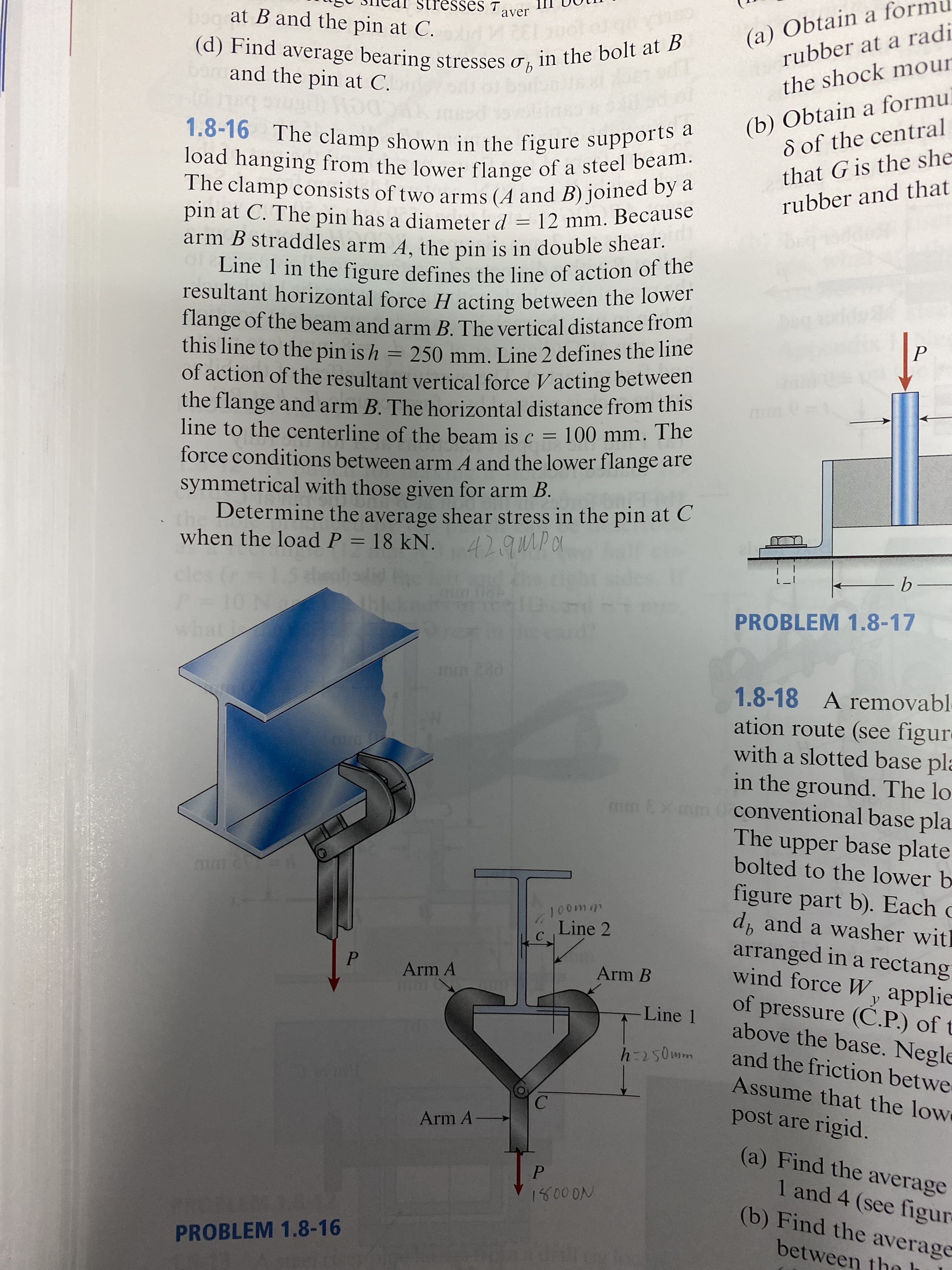
1.8-16 The clamp shown in the figure supports a load hanging from the lower flange of a steel beam. The clamp consists of two arms (A and B) joined by a pin at C. The pin has a diameter d = 12 mm. Because arm B straddles arm A, the pin is in double shear. Line 1 in the figure defines the line of action of the resultant horizontal force H acting between the lower flange of the beam and arm B. The vertical distance from this line to the pin is h of action of the resultant vertical force Vacting between the flange and arm B. The horizontal distance from this line to the centerline of the beam is c = force conditions between arm A and the lower flange are symmetrical with those given for arm B. Determine the average shear stress in the pin at C %3D 250 mm. Line 2 defines the line 100 mm. The when load P = 18 kN.


1.8-16 The clamp shown in the figure supports a load hanging from the lower flange of a steel beam. The clamp consists of two arms (A and B) joined by a pin at C. The pin has a diameter d = 12 mm. Because arm B straddles arm A, the pin is in double shear. Line 1 in the figure defines the line of action of the resultant horizontal force H acting between the lower flange of the beam and arm B. The vertical distance from this line to the pin is h of action of the resultant vertical force Vacting between the flange and arm B. The horizontal distance from this line to the centerline of the beam is c = force conditions between arm A and the lower flange are symmetrical with those given for arm B. Determine the average shear stress in the pin at C %3D 250 mm. Line 2 defines the line 100 mm. The when load P = 18 kN.


Trending now
This is a popular solution!

Step by step
Solved in 4 steps with 1 images


