
Concept explainers
Videos
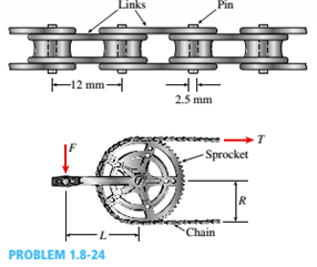
A bicycle chain consists of a series of small links, where each are 12 mm long between the centers of the pins (see figure). You might wish to examine a bicycle chain and observe its construction. Note particularly the pins, which have a diameter of 2.5 mm.
To solve this problem, make two measurements on a bicycle (see figure): (1) the length L of the crank arm from main axle to pedal axle and (2) the radius R of the sprocket (the toothed wheel, sometimes called the chainring).
(a) Using your measured dimensions, calculate the tensile force T in the chain due to a force F = 800 N applied to one of the pedals.
(b) Calculate the average shear stress T averin the pins.

Trending nowThis is a popular solution!

Chapter 1 Solutions
Mechanics of Materials (MindTap Course List)


- Around brass bar of a diameter d1= 20mm has upset ends each with a diameter d2= 26 mm (see figure). The lengths of the segments of the bar are L1= 0.3 m and L2= 0.1 m. Quarter-circular fillets are used at the shoulders of the bar, and the modulus of elasticity of the brass is E = 100 GPa. If the bar lengthens by 0.12 mm under a tensile load P, what is the maximum stress ??maxin the bar?arrow_forwardA solid steel bar of diameter d1= 1.50 in. is enclosed by a steel tube of outer diameter d3= 2.25 in, and inner diameter d2= 1,75 in. (see figure). Both bar and tube arc held rigidly by a support at end A and joined securely to a rigid plate at end B. The composite bar, which has length L = 30.0 in., is twisted by a torque T = 5000 lb-in, acting on the end plate. Determine the maximum shear stresses r, and r2in the bar and tube, respectively. Determine the angle of rotation 0 (in degrees) of the end plate, assuming that the shear modulus of the steel is G = 116 × 106 psi. Determine the torsional stiffness kTof the composite bar.arrow_forwardThe L-shaped arm ABCD shown in the figure lies in a vertical plane and pivots about a horizontal pin at A. The arm has a constant cross-sectional area and total weight W. A vertical spring of stiffness k supports the arm at point B. (a) Obtain a formula for the elongation of the spring due to the weight of the arm. (b) Repeat part (a) if the pin support at A is moved to D.arrow_forward
- Two pipe columns (AB, FC) are pin-connected to a rigid beam (BCD), as shown in the figure. Each pipe column has a modulus of E, but heights (L1or L2) and outer diameters (d1or different for each column. Assume the inner diameter of each column is 3/4 of outer diameter. Uniformly distributed downward load q = 2PIL is applied over a distance of 3L/4 along BC, and concentrated load PIA is applied downward at D. (a) Derive a formula for the displacementarrow_forwardWires B and C are attached to a support at the left-hand end and to a pin-supported rigid bar at the right-hand end (see figure). Each wire has cross-sectional area A =0.03 in2 and modulus of elasticity E = 30 X 106 psi. When the bar is in a vertical position, the length of each wire is L = 80 in. However, before being attached to the bar, the length of wire B was 79.98 in. and wire C was 79.95 in. Find the tensile forces TBand Tc in the wires under the action of a force P = 700 lb acting at the upper end of the bar.arrow_forwardA plastic rod AB of length L = 0.5 m has a diameter d1= 30 mm (see figure). A plastic sleeve CD of length c = 0.3 m and outer diameter d2= 45 mm is securely bonded to the rod so that no slippage can occur between the rod and the sleeve. The rod is made of an acrylic with a modulus of elasticity E1= 3.1 GPa, and the sleeve is made of a polyamide with E2= 2.5 GPa. (a) Calculate the elongation d of the rod when it is pulled by axial forces P = 12 kN. (b) If the sleeve is extended for the full length of the rod, what is the elongation? (c) If the sleeve is removed, what is the elongation?arrow_forward
- A uniform bar AB of weight W = 25 N is supported by two springs, as shown in the figure. The spring on the left has a stiffness k[= 300 N/m and natural length Lt=250 mm. The corresponding quantities for the spring on the right are k2= 400 N/m and L^ = 200 mm. The distance between the springs is L = 350 mm, and the spring on the right is suspended from a support that is a distance it = SO mm below the point of support for the spring on the left. Neglect the weight of the springs. (a) At what distance x from the left-hand spring (figure part a) should a load P = 18 N be placed in order to bring the bar to a horizontal position? (b) If P is now removed, what new value of k{is required so that the bar (figure part a) will hang in a horizontal position underweight If? (c) If P is removed and kt= 300 N/m. what distance b should spring ktbe moved to the right so that the bar (figure part a) will hang in a horizontal position under weight II"? (d) If the spring on the left is now replaced by two springs in series (kt= 300 N/m, kt) with overall natural length Lt= 250 mm (see figure part b). what value of k; is required so that the bar will hang in a horizontal position under weight IF?arrow_forwardA steel riser pipe hangs from a drill rig located offshore in deep water (see figure). Separate segments are joined using bolted flange plages (see figure part b and photo). Assume that there are six bolts at each pipe segment connection. Assume that the total length of the riser pipe is L = 5000 ft: outer and inner diameters are d2= l6in.and d1= 15 in.; flange plate thickness t1= 1.75 in.; and bolt and washer diameters are db= 1.125 in..and dW. = 1.875 in., respectively. (a) If the entire length of the riser pipe is suspended in air. find the average normal stress a in each bolt, the average bearing stress abbeneath each washer, and the average shear stress t through the flange plate at each bolt location for the topmost bolted connection. (b) If the same riser pipe hangs from a drill rig at sea. what are the normal, bearing, and shear stresses in the connection? Obtain the weight densities of steel and sea water from Table I-1. Appendix I. Neglect the effect of buoyant foam casings on the riser pipearrow_forwardTwo rigid bars are connected to each other by two linearly elastic springs. Before loads are applied, the lengths or the springs are such, that the bars are parallel and the springs are without stress. (a) Derive a formula for the displacement E4at point 4 when the load P is applied at joint 3 and moment PL is applied at joint 1. as shown in the figure part a. (Assume that the bars rotate through very small angles under the action of load P.) (b) Repeat part (a) if a rotational spring, kr= kL2, is now added at joint 6. What is the ratio of the deflection d4 in the figure part a to that in the figure part b ?arrow_forward
- A steel riser pipe hangs from a drill rig. Individual segments of equal length L = 50 ft are joined to get her using bolted flange plates (see figure part b). There are six bolts at each pipe segment connection. The outer and inner pipe diameters are t2= 14 in. and d1= 13 in.; flange plate thickness tf= 1.5 in.; and boll and washer diameters are db= 1.125 in. and dn. = 1.875 in. Find the number n of permissible segments of pipe based on following allowable stresses. (a) The allowable tensile stress in the pipe is 50 ksi. (b) The allowable tensile stress in a bolt is 120 ksi. Find number of segments n for two cases: pipe hanging in air and pipe hanging in seawater.arrow_forwardAn L-shaped reinforced concrete slab 12 Ft X 12 ft, with a 6 Ft X 6 ft cut-out and thickness t = 9.0 in, is lifted by three cables attached at O, B, and D, as shown in the figure. The cables are are combined at point Q, which is 7.0 Ft above the top of the slab and directly above the center of mass at C. Each cable has an effective cross-sectional area of Ae= 0.12 in2. (a) Find the tensile force Tr(i = 1, 2, 3) in each cable due to the weight W of the concrete slab (ignore weight of cables). (b) Find the average stress ov in each cable. (See Table I-1 in Appendix I for the weight density of reinforced concrete.) (c) Add cable AQ so that OQA is one continuous cable, with each segment having Force T, which is connected to cables BQ and DQ at point Q. Repeat parts (a) and (b). Hini: There are now three Forced equilibrium equations and one constrain equation, T1= T4.arrow_forwardA circular tube of inner radius r1and outer radius r2is subjected to a torque produced by forces P = 900 lb (see figure part a). The forces have their lines of action at a distance b = 5.5 in. from the outside of the tube. (a) If the allowable shear stress in the tube is 6300 psi and the inner radius r1= 1.2 in., what is the minimum permissible outer radius r2? (b) If a torsional spring of stiffness = 450 kip-in./rad is added at the end of the tube (see figure part b), what is the maximum value of forces P lithe allowable shear stress is not to be exceeded? Assume that the tube has a length of L 18 in., outer radius of r2= 1.45 in. and shear modulus G = 10.800 ksi. Hint: Consider the tube and torsional spring as “springs in parallel.”arrow_forward
 Mechanics of Materials (MindTap Course List)Mechanical EngineeringISBN:9781337093347Author:Barry J. Goodno, James M. GerePublisher:Cengage Learning