
Concept explainers
Videos
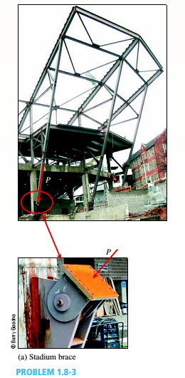
The upper deck ala foothill stadium is supported by braces, each of which transfer a load
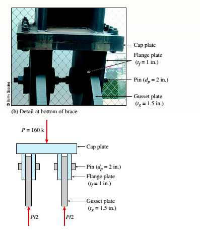
P = 160 kips to the base of a column (see figure part a). A cap plate at the bottom of the brace distributes the load P to four flange pates (:1 = I in)t hrough a pin(d, = 2 in.) to two gusset plates
t8 = l.5 in.) (see figure parts b and c).
Determine the following quantities.
(a) The average shear stress i in the pin.
(b) The average bearing stress between the flange plates and the pin and also between the gusset plates and the pin Disregard friction between the plates.
Determine the following quantities.
(a) The average shear stress i in the pin.
(b) The average bearing stress between the flange plates and the pin and also between the gusset plates and the pin (7j )L
Disregard friction between the plates.

Trending nowThis is a popular solution!

Chapter 1 Solutions
Mechanics of Materials (MindTap Course List)


- Two pipe columns (AB, FC) are pin-connected to a rigid beam (BCD), as shown in the figure. Each pipe column has a modulus of E, but heights (L1or L2) and outer diameters (d1or different for each column. Assume the inner diameter of each column is 3/4 of outer diameter. Uniformly distributed downward load q = 2PIL is applied over a distance of 3L/4 along BC, and concentrated load PIA is applied downward at D. (a) Derive a formula for the displacementarrow_forwardA column ABC is supported at ends A and C and compressed by an axial load P (figure a). Lateral support is provided at point B but only in the plane of the figure; lateral support perpendicular to the plane of the figure is provided only at A and C. The column is constructed of two channel sections (C 6 × 8.2) back to back (see figure b). The modulus of elasticity of the column is E = 29,500 ksi and the proportional limit is 50 ksi. The height of the column is L = 15 ft. Find the allowable value of load P using a factor of safety of 2.5.arrow_forward-21 Plastic bar AB of rectangular cross section (6 = 0.75 in. and h = 1.5 in.) and length L = 2 Ft is Fixed at A and has a spring support (Ar = 18 kips/in.) at C (see figure). Initially, the bar and spring have no stress. When the temperature of the bar is raised hy foot. the compressive stress on an inclined plane pq at Lq = 1.5 Ft becomes 950 psi. Assume the spring is massless and is unaffected by the temperature change. Let a = 55 × l0-6p and E = 400 ksi. (a) What is the shear stresst9 on plane pq? What is angle 07 =1 Draw a stress element oriented to plane pq, and show the stresses acting on all laces of this element. (c) If the allowable normal stress is ± 1000 psi and the allowable shear stress is ±560 psi, what is the maximum permissible value of spring constant k if the allowable stress values in the bar are not to be exceeded? (d) What is the maximum permissible length L of the bar if the allowable stress values in the bar are not be exceeded? (Assume £ = IB kips/in.) (e) What is the maximum permissible temperature increase (A7") in the bar if the allowable stress values in the bar are not to be exceeded? (Assume L = 2 ft and k = L& kips/inarrow_forward
- A long, rectangular copper bar under a tensile load P hangs from a pin that is supported by two steel posts (see figure). The copper bar has a length of 2.0 m, a cross-sectional area of4S00 mm", and a modulus of elasticity Ec= 120 GPa. Each steel post has a height of 0.5 m, a cross-sectional area of 4500 mm2, and a modulus of elasticity E = 200 GRa. (a) Determine the downward displacementarrow_forwardA weight W = 4500 lb falls from a height h onto a vertical wood pole having length L = 15 ft, diameter d = 12 in., and modulus of elasticity E = 1.6 × 10⁶ psi (see figure). If the allowable stress in the wood under an impact load is 2500 psi. what is the maximum permissible height h?arrow_forwardA plane truss is subjected to loads 2P and P at joints B and C, respectively, as shown in the figure part a. The truss bars are made of two L 102 X 76 X 6.4 steel angles (see Table F-5(b): cross-sectional area or the two angles, A = 2180 mm2, and figure part b) having an ultimate stress in tension equal to 390 MPa. The angles are connected to a 12-mm-thick gusset plate at C(figure part c) with 16-mm diameter rivets; assume each rivet transfers an equal share of the member force to the gusset plate. The ultimate stresses in shear and bearing for the rivet steel are 190 MPa and 550 MPa, respectively. Determine the allowable load Pallowif a safety factor of 2.5 is desired with respect to the ultimate load that can be carried. Consider tension in the bars, shear in the rivets, bearing between the rivets and gusset plate. Disregard friction between the plates the bars, and also bearing between the rivets and the and the weight of the truss itself.arrow_forward
- A plastic bar of rectangular cross section (ft = 1.5 in. and h = 3 in.) fits snugly between rigid supporls at room temperature (68oF) but with no initial stress (see Figure). When the temperature of the bar is raised to 160oF, the compressive stress on an inclined plane pq at mid-span becomes 1700 psi. (a) What is the shear stress on plane pq? (Assume a = 60 × 10-6/*t and E = 450 × 103psi.) (b) Draw a stress element oriented to plane pq and show the stresses acting on all laces of this element. (c) If the allowable normal stress is 3400 psi and the allowable shear stress is 1650 psi. what is the maximum load P (in the positive x direction), which can be added at the quarter point (in addition to thermal effects given) without exceeding allowable stress values in the bar?arrow_forwardA square steel tube of a length L = 20 ft and width b2= 10.0 in. is hoisted by a crane (see figure). The lube hangs from a pin of diameter d that is held by the cables at points A and B. The cross section is a hollow square with an inner dimension b1= 8.5 in. and outer dimension b2= 10,0 in. The allowable shear stress in the pin is 8,700 psi. and the allowable bearing stress between the pin and the tube is 13,000 psi. Determine the minimum diameter of the pin in order to support the weight of the tube. Note: Disregard the rounded corners of the tube when calculating its weight.arrow_forwardThe horizontal beam ABC shown in the figure is supported by columns BD and CE. The beam is prevented from moving horizontally by the pin support at end A. Each column is pinned at its upper end to the beam, but at the lower ends, support D is a sliding support and support E is pinned. Both co lu in us arc solid steel bars (E = 30 × 106 psi) of square cross section with width equal to 0.625 in. A load Q acts at distance a from column BD. If the distance a = 12 in., what is the critical value Qcr of the load? If the distance a can be varied between 0 and 40 in., what is the maximum possible value of Qcr? What is the corresponding value of the distance a?arrow_forward
- A rigid bar AB having a mass M = 1.0 kg and length L = 0.5 m is hinged at end A and supported at end B by a nylon cord BC (see figure). The record has cross-sectional area A = 30 mm2. length b = 0.25 m. and modulus of elasticity E = 2.1 GPa. If the bar is raised to its maximum height and then released, what is the maximum stress in the cord?arrow_forwardBar ABC is fixed at both ends (see figure) and has load P applied at B. Find reactions at A and C and displacement SBif P = 200 kN. L = 2 m, t = 20 mm, b, = 100 mm, b2= 115 mm, and E = 96 GPa.arrow_forwardA hollow circular tube T of a length L = 15 in. is uniformly compressed by a force P acting through a rigid plate (see figure). The outside and inside diameters of the tube are 3.0 and 2.75 in., respectively. A concentric solid circular bar B of 1.5 in. diameter is mounted inside the lube. When no load is present, there is a clearance c = 0.0I0 in. between the bar B and the rigid plate. Both bar and tube are made of steel having an c[autoplastic stress-strain diagram with E = 29 X LO3 ksi and err= 36 ksi. (a) Determine the yield load Pt- and the corresponding shortening 3yof the lube. (b) Determine the plastic load Ppand the corresponding shortening Spof the tube. (c) Construct a load-displacement diagram showing the load Pas ordinate and the shortening 5 of the tube as abscissa. Hint: The load-displacement diagram is not a single straight line in the region 0 ^ P ^ Prarrow_forward
 Mechanics of Materials (MindTap Course List)Mechanical EngineeringISBN:9781337093347Author:Barry J. Goodno, James M. GerePublisher:Cengage Learning