
Concept explainers
Videos
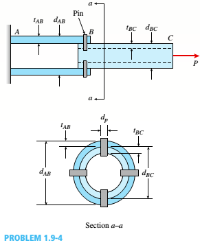
Two steel tubes are joined at B by four pins (dp= 11 mm), as shown in the cross section a—a in the fiaure. The outer diameters of the tubes are dAB= 41 mm and dBC= 28 mm. The wall thickness are tAB= 6.5 mm and tBC= 7.5 mm. The yield stress in tension for the steel is sy = 200 MPa and the ultimate stress in tension is ??U:= 340 MPa. The corresponding yield and ultimate values in shear for the pm are 80 MPa and 140 MPa, respectively. Finally, the yield and ultimate values in bearing R between the pins and the tubes are 260 MPa, and 450 MPa, respectively. Assume that the factors safety with respect to yield stress and ultimate stress are 3.5 and 4.5. respectively. (a) Calculate the allowable tensile force P allowconsidering tension in the tube (b) Recompute P allowfor shear in the pins.(c)Finaly, recomputed Pallowfor bearing between the pm and the tubes. Which is the tubes. Which is the controlling value value of P?

Trending nowThis is a popular solution!

Chapter 1 Solutions
Mechanics of Materials (MindTap Course List)


- A hollow, circular, cast-iron pipe (Ec =12,000 ksi) supports a brass rod (Ec= 14,000 ksi} and weight W — 2 kips, as shown. The outside diameter of the pipe is dc= 6 in. (a) If the allowable compressive stress in the pipe is S00O psi and the allowable shortening of the pipe is 0.02 in., what is the minimum required wall thickness trmm? (Include the weights of the rod and steel cap in your calculations.) (b) What is the elongation of the brass rod Srdue to both load Wand its own weight? (c) What is the minimum required clearance h?arrow_forwardA tie-down on the deck of a sailboat consists of a bent bar boiled at both ends, as shown in the figure. The diameter dBof the bar is 1/4 in., the diameter D Wof the washers is 7/8 in., and the thickness is of the fiberglass deck is 3/8 in. If the allowable shear stress in the fiberglass is 300 psi, and the allowable bearing pressure between the washer and the fiberglass is 550 psi, what is the allowable load P allowon the tie-down?arrow_forwardA hollow circular tube T of a length L = 15 in. is uniformly compressed by a force P acting through a rigid plate (see figure). The outside and inside diameters of the tube are 3.0 and 2.75 in., respectively. A concentric solid circular bar B of 1.5 in. diameter is mounted inside the lube. When no load is present, there is a clearance c = 0.0I0 in. between the bar B and the rigid plate. Both bar and tube are made of steel having an c[autoplastic stress-strain diagram with E = 29 X LO3 ksi and err= 36 ksi. (a) Determine the yield load Pt- and the corresponding shortening 3yof the lube. (b) Determine the plastic load Ppand the corresponding shortening Spof the tube. (c) Construct a load-displacement diagram showing the load Pas ordinate and the shortening 5 of the tube as abscissa. Hint: The load-displacement diagram is not a single straight line in the region 0 ^ P ^ Prarrow_forward
- A circular aluminum tube with pinned ends supports a load P = 18 kN acting at a distance e = 50 mm from the center (see figure). The length of the tube is 3.5 m, and its modulus of elasticity is 73 GPa. If the maximum permissible stress in the tube is 20 MPa, what is the required outer diameter d2if the ratio of diameters is to be d1/ d2= 0.9?arrow_forwardA two-story building has steel columns AB in the first floor and BC in the second floor, as shown in the figure. The roof load P:equals 400 KN, and the second-floor load P-, equals 720 kN. Each column has a length L = 3.75 m. The cross-sectional areas of the first- and second-floor columns are 11,000 mm" and 3900 mm", respectively. (a) Assuming that E = 206 GPa. determine the total shortenings aof the two columns due to the combined action of the loads Ptand P,. (b) How much additional load P0can be placed at t he top of t he column (point C) if t he total shortening: SACis not to exceed 4.0 mm?arrow_forwardA W410 × S5 steel column is compressed by a force P = 340 kN acting with an eccentricity e = 38 mm, as shown in the figure. The column has pinned ends and a length L. Also, the steel has a modulus of elasticity E = 200 GPa and yield stress y= 250 MPa. P = 340 kN If the length L = 3 m, what is the maximum compressive stress maxin (he column? If a factor of safety n =2.0 is required with respect to yielding, what is the longest permissible length Lmaxof the column?arrow_forward
- -21 Plastic bar AB of rectangular cross section (6 = 0.75 in. and h = 1.5 in.) and length L = 2 Ft is Fixed at A and has a spring support (Ar = 18 kips/in.) at C (see figure). Initially, the bar and spring have no stress. When the temperature of the bar is raised hy foot. the compressive stress on an inclined plane pq at Lq = 1.5 Ft becomes 950 psi. Assume the spring is massless and is unaffected by the temperature change. Let a = 55 × l0-6p and E = 400 ksi. (a) What is the shear stresst9 on plane pq? What is angle 07 =1 Draw a stress element oriented to plane pq, and show the stresses acting on all laces of this element. (c) If the allowable normal stress is ± 1000 psi and the allowable shear stress is ±560 psi, what is the maximum permissible value of spring constant k if the allowable stress values in the bar are not to be exceeded? (d) What is the maximum permissible length L of the bar if the allowable stress values in the bar are not be exceeded? (Assume £ = IB kips/in.) (e) What is the maximum permissible temperature increase (A7") in the bar if the allowable stress values in the bar are not to be exceeded? (Assume L = 2 ft and k = L& kips/inarrow_forwardAround brass bar of a diameter d1= 20mm has upset ends each with a diameter d2= 26 mm (see figure). The lengths of the segments of the bar are L1= 0.3 m and L2= 0.1 m. Quarter-circular fillets are used at the shoulders of the bar, and the modulus of elasticity of the brass is E = 100 GPa. If the bar lengthens by 0.12 mm under a tensile load P, what is the maximum stress ??maxin the bar?arrow_forwardA vertical pole of aluminum is fixed at the base and pulled at the top by a cable having a tensile force T(see figure). The cable is attached at the outer edge of a stiffened cover plate on top of the pole and makes an angle a = 20° at the point of attachment. The pole has length a = 2.5 m and a hollow circular cross section with an outer diameter d2= 280 mm and inner diameter d1= 220 mm. The circular cover plate has diameter 1.5d2 Determine the allowable tensile force Tallow in the cable if the allowable compressive stress in the aluminum pole is 90 MPa.arrow_forward
- A square steel tube of a length L = 20 ft and width b2= 10.0 in. is hoisted by a crane (see figure). The lube hangs from a pin of diameter d that is held by the cables at points A and B. The cross section is a hollow square with an inner dimension b1= 8.5 in. and outer dimension b2= 10,0 in. The allowable shear stress in the pin is 8,700 psi. and the allowable bearing stress between the pin and the tube is 13,000 psi. Determine the minimum diameter of the pin in order to support the weight of the tube. Note: Disregard the rounded corners of the tube when calculating its weight.arrow_forwardA post having a hollow, circular cross section supports a P = 3.2 kN load acting at the end of an arm that is h = 1.5 m long (see figure). The height of the post is L = 9 m, and its section modulus isS = 2.65 x 10 mmJ. Assume that the outer radius of the post is r2= 123 mm, and the inner radius is r}=117 mm. (a) Calculate the maximum tensile stress and \ maximum in-plane shear stress Tm:ls at point A on the outer surface of the post along the x axis due to the load P. Load P acts at B along line BC. (b) If the maximum tensile stress and maximum in-plane shear stress at point A arc limited to 90 MPa and 38 MPa, respectively, what is the largest permissible value of the load PIarrow_forwardA long, rectangular copper bar under a tensile load P hangs from a pin that is supported by two steel posts (see figure). The copper bar has a length of 2.0 m, a cross-sectional area of4S00 mm", and a modulus of elasticity Ec= 120 GPa. Each steel post has a height of 0.5 m, a cross-sectional area of 4500 mm2, and a modulus of elasticity E = 200 GRa. (a) Determine the downward displacementarrow_forward
 Mechanics of Materials (MindTap Course List)Mechanical EngineeringISBN:9781337093347Author:Barry J. Goodno, James M. GerePublisher:Cengage Learning