Videos
A matching network consists of a length of a T-line through section in series with a capacitor. Determine the length (in wavelengths) required of the through section and the capacitor value needed (at 1.0 GHz) to match a
The length of section that consists of a capacitor in series and the value of capacitor for matched network.
Answer to Problem 10.1P
The length of section is
Explanation of Solution
Given:
The load impedance is
Calculation:
The Smith chart for the matched network is shown in Figure 1.
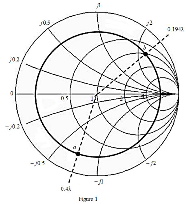
From the Smith chart, the value of normalized load is
The normalized load at the point
The length of the section of matched network is calculated as,
Therefore, the length of the section is
The value of series capacitance is calculated as,
Substitute
Therefore, the capacitance is
Conclusion:
Thus, the length of section is
Want to see more full solutions like this?
Chapter 10 Solutions
Fundamentals of Electromagnetics with Engineering Applications


- At 3 GHz, a shorted parallel sideline will be used to match a 60 ohm transmission line to a load impedance of ZL = 30 - j60 ohms. What should be the length of the parallel lateral line, in mm? Calculate using the Smith diagram.arrow_forwardA lossless transmission line has a Zo of 50 ohms and a line velocity of 2.4 x 10^8 m/s. If the operating frequency is 1 MHz. Determine the capacitance in pf.arrow_forwarda) Find the shortest length of this open tranmission line that appears at the input as a capacitor of 5 pF at 2.5 GHz. b) Repeat for the inductance of 5 nH.arrow_forward
- A wireless communication system has a trasmit power Pt = 10 mW. Through extensive measurements, the path gain of the system at the reference distance is determined to be -32 dB, and the path loss exponent to be 3.8. Using the simplified path loss model, find the received power in mW at distance 200 meters from the transmitterarrow_forwardA satellite transmitter operates at 4 GHz with an antenna gain of 40 dBi. The receiver 40,000 km away has a gain of 50 dBi. If the transmitter has a power 8 W, ignoring feedline losses and mismatch, find (a) the EIRP in dBW (b) the free space path loss, (c) the power delivered to the receiver in W and dBmarrow_forwardSince a 50 ohm transmission line with phase constant (π/10) rad/m will be used at 500 MHz, what is the inductance of the line per unit length, in nH/m?arrow_forward
- Calculate the charecterictics impedance, propagation constant and velocity of propagation at 600 KHz for a transmission line having L=0.5Mh/km and C=.08microfarad/km,and and negligible R and G.arrow_forwardA 50Ω lossless transmission line is terminated in a load (50+j100) Ω. Using a smith chart, determine the reflection coefficient.arrow_forwardA 350 km transmission line has the following parameters: z = 0.0195 +j0.35 Ω/km y = j4.5 μS/km If the load served by the line is 300 MVA, with an fp of 0.8(-), at a voltage of 100√3KV say: 6. The value of the incident and reflected wave, as well as the total voltage, at a point 200 km away from the extreme load. 7. The voltage and current at the emitting end. 8. What would be the percentage error in the magnitude of the voltage VS if it is calculated with the lossless line model? lossless line model? Note that the accurate value is the one that takes losses into account.arrow_forward
- The height of base station is 200 meter and operated at 2600MHz. The gain of the base station antenna (transmitter) and the receiving antenna (mobile phone) are 20 dB and 6 dB, respectively. The distance between base station and mobile phone is 2 km. a) Find the free space transmission loss. b) Find the power received when the transmitted power is 60 W.arrow_forwardSince S = 1.7 in a transmission line to be used at 2 GHz; What is the length, in cm, of the parallel lateral line required to match the transmission line to the load impedance?arrow_forwardA 350 km transmission line has the following parameters: z = 0.0195 +j0.35 Ω/km y = j4.5 μS/km If the load served by the line is 300 MVA, with an fp of 0.8(-), at a voltage of 100√3KV say: 6. The value of the incident and reflected wave, as well as the total voltage, at a point 200 km from the end of the load. 7. The voltage and current at the emitting end. 8. What would be the percentage error in the magnitude of the voltage VS if it is calculated with the lossless line model? lossless line model? Note that the accurate value is the one that takes losses into account.arrow_forward
 Introductory Circuit Analysis (13th Edition)Electrical EngineeringISBN:9780133923605Author:Robert L. BoylestadPublisher:PEARSON
 Delmar's Standard Textbook Of ElectricityElectrical EngineeringISBN:9781337900348Author:Stephen L. HermanPublisher:Cengage Learning
 Programmable Logic ControllersElectrical EngineeringISBN:9780073373843Author:Frank D. PetruzellaPublisher:McGraw-Hill Education
 Fundamentals of Electric CircuitsElectrical EngineeringISBN:9780078028229Author:Charles K Alexander, Matthew SadikuPublisher:McGraw-Hill Education
 Electric Circuits. (11th Edition)Electrical EngineeringISBN:9780134746968Author:James W. Nilsson, Susan RiedelPublisher:PEARSON
 Engineering ElectromagneticsElectrical EngineeringISBN:9780078028151Author:Hayt, William H. (william Hart), Jr, BUCK, John A.Publisher:Mcgraw-hill Education,