
Concept explainers
Videos
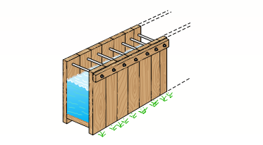
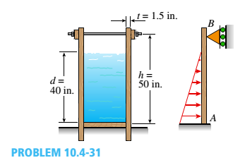
A temporary wood flume serving as a channel for irrigation water is shown in the figure. The vertical boards forming the sides of the flume are sunk in the ground, which provides a fixed support. The top of the flume is held by tic rods that are tightened so that there is no deflection of the boards at that point. Thus, the vertical boards may be modeled as a beam AB, supported and loaded as shown in the last part of the figure.
Assuming that the thickness t of the boards is 1,5 in., the depth d of the water is 40 in., and the height h to the tie rods is 50 in., what is the maximum bending stress

Trending nowThis is a popular solution!

Chapter 10 Solutions
Mechanics of Materials (MindTap Course List)


- A cylindrical brick chimney of height H weighs w = 825 lb/ft of height (see figure). The inner and outer diameters are d1= 3 ft and d2= 4 ft, respectively. The wind pressure against the side of the chimney is p = 10 lb/ft2 of projected area. Determine the maximum height H if there is to be no tension in the brickwork.arrow_forwardA large precast concrete panel for a warehouse is raised using two sets of cables at two lift lines, as shown in the figure part a. Cable 1 has a length L1 = 22 Ft, cable 2 has a length L2= 10 ft, and the distance along the panel between lift points Band D is d = 14 ft (see figure part b). The total weight of the panel is W = 85 kips. Assuming the cable lift Forces F at each lift line are about equal, use the simplified model of one half of the panel in figure part b to perform your analysis for the lift position shown. Find the required cross-sectional area AC of the cable if its breaking stress is 91 ksi and a factor of safety of 4 with respect to failure is desired.arrow_forwardA foot bridge on a hiking trail is constructed using two timber logs each having a diameter d = 0.5 m (see figure a). The bridge is simply supported and has a length L = 4 m. The top of each log is trimmed to form the walking surface (see Fig, b)LA simplified model of the bridge is shown in Fig. g. Each log must carry its own weight w = 1.2 kN/m and the weight (P = 850 N) of a person at mid-span, (see Fig. b). Determine the maximum tensile and compressive stresses in the beam (Fig, b) due to bending. If load h is unchanged, find the maximum permissible value of load ... if the allowable normal stress in tension and compression is 2.5 M Pa.arrow_forward
- An L-shaped reinforced concrete slab 12 Ft X 12 ft, with a 6 Ft X 6 ft cut-out and thickness t = 9.0 in, is lifted by three cables attached at O, B, and D, as shown in the figure. The cables are are combined at point Q, which is 7.0 Ft above the top of the slab and directly above the center of mass at C. Each cable has an effective cross-sectional area of Ae= 0.12 in2. (a) Find the tensile force Tr(i = 1, 2, 3) in each cable due to the weight W of the concrete slab (ignore weight of cables). (b) Find the average stress ov in each cable. (See Table I-1 in Appendix I for the weight density of reinforced concrete.) (c) Add cable AQ so that OQA is one continuous cable, with each segment having Force T, which is connected to cables BQ and DQ at point Q. Repeat parts (a) and (b). Hini: There are now three Forced equilibrium equations and one constrain equation, T1= T4.arrow_forwardA steel riser pipe hangs from a drill rig located offshore in deep water (see figure). (a) What is the greatest length (meters) it can have without breaking if the pipe is suspended in the air and the ultimate strength (or breaking strength) is 550 MPa? (b) If the same riser pipe hangs from a drill rig at sea, what is the greatest length? (Obtain the weight densities of steel and sea water from Table M, Appendix I. Neglect the effect of buoyant foam casings on the pipe.)arrow_forwardTwo pipe columns (AB, FC) are pin-connected to a rigid beam (BCD), as shown in the figure. Each pipe column has a modulus of E, but heights (L1or L2) and outer diameters (d1or different for each column. Assume the inner diameter of each column is 3/4 of outer diameter. Uniformly distributed downward load q = 2PIL is applied over a distance of 3L/4 along BC, and concentrated load PIA is applied downward at D. (a) Derive a formula for the displacementarrow_forward
- The compound beam shown in the figure consists of a cantilever beam AB (length L) that is pin-connected to a simple beam BD (length 2L). After the beam is constructed, a clearance c exists between the beam and a support at C, midway between points B and ZX Subsequently, a uniform load is placed along the entire length of the beam. What intensity q of the load is needed to close the gap at C and bring the beam into contact with the support?arrow_forwardThe L-shaped arm ABCD shown in the figure lies in a vertical plane and pivots about a horizontal pin at A. The arm has a constant cross-sectional area and total weight W. A vertical spring of stiffness k supports the arm at point B. (a) Obtain a formula for the elongation of the spring due to the weight of the arm. (b) Repeat part (a) if the pin support at A is moved to D.arrow_forwardThe main cables of a suspension bridge (see figure part a) follow a curve that is nearly parabolic because the primary load on the cables is the weight of the bridge deck, which is uniform in intensity along the horizontal. Therefore, represent the central region AOB of one of the main cables (see part b of the figure) as a parabolic cable supported at points A and B and carrying a uniform load of intensity q along the horizontal. The span of the cable is L, the sag is /i, the axial rigidity is EA\ and the origin of coordinates is at mid span. (a) Derive the following formula for the elongation of cable AOB shown in part b or the figure: (b) Calculate the elongation 5 of the central span of one of the main cables of the Golden Gate Bridge for which the dimensions and properties are L = 4200 ft,h = 470 ft, q = 12,700 lb/ft, and E = 23,300,000 psi The cable consists of 27,572 parallel wires of diameter 0.196 in. Hint: Determine the tensile force Tal any point in the cable from a free-body diagram of part of the cable; then determine the elongation of an element of the cable of length ds: finally, integrate along the curve of the cable to obtain an equation for the elongation £.arrow_forward
- A long re Lai nine: wall is braced by wood shores set at an angle of 30° and supported by concrete thrust blocks, as shown in the first part of the figure. The shores are evenly spaced at 3 m apart. For analysis purposes, the wall and shores are idealized as shown in the second part of the figure. Note that the base of the wall and both ends of the shores are assumed to be pinned. The pressure of the soil against the wall is assumed to be triangularly distributed, and the resultant force acting on a 3-meter length of the walls is F = 190 kN. If each shore has a 150 mm X 150 mm square cross section, what is the compressive stressarrow_forwardA fixed-end beam AB of a length L is subjected to a uniform load of intensity q acting over the middle region of the beam (sec figure). Obtain a formula for the fixed-end moments MAand MBin terms of the load q, the length L, and the length h of the loaded part of the beam. Plot a graph of the fixed-end moment MAversus the length b of the loaded part of the beam. For convenience, plot the graph in the following nondimensional form: MAqL2/l2versusbL with the ratio b/L varying between its extreme values of 0 and 1. (c) For the special case in which ù = h = L/3, draw the shear-force and bending-moment diagrams for the beam, labeling all critical ordinates.arrow_forwardA C 200 x 17.1 channel section has an angle with equal legs attached as shown; the angle serves as a lintel beam. The combined steel section is subjected to a bending moment M having its vector directed along the z axis, as shown in the figure. The cent roi d C of the combined section is located at distances xtand ycfrom the centroid (C1) of the channel alone. Principal axes yl and yvare also shown in the figure and properties Ix1,Iy1and 0pare given. Find the orientation of the neutral axis and calculate the maximum tensile stress exand maximum compressive stress if the angle is an L 76 x 76 x 6.4 section and M = 3.5 kN - m. Use the following properties for principal axes for the combined section:/^, = 18.49 X 10⁶ nrai4,/;| = 1.602 X 106 mm4, ep= 7.448*(CW),_r£ = 10.70 mm,andvf= 24.07 mm.arrow_forward
 Mechanics of Materials (MindTap Course List)Mechanical EngineeringISBN:9781337093347Author:Barry J. Goodno, James M. GerePublisher:Cengage Learning