
Mechanics of Materials (MindTap Course List)
9th Edition
ISBN: 9781337093347
Author: Barry J. Goodno, James M. Gere
Publisher: Cengage Learning
expand_more
expand_more
format_list_bulleted
Concept explainers
Videos
Textbook Question
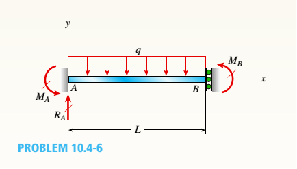
Chapter 10, Problem 10.4.6P
A beam with a sliding support at B is loaded by a uniformly distributed load with intensity q. Use the method of superposition to solve for all reactions. Also draw shear-force and bending-moment diagrams, labeling all critical ordinales.
Expert Solution & Answer

Trending nowThis is a popular solution!

Students have asked these similar questions
A beam with a sliding support at B is loadedby a uniformly distributed load with intensity q. Usethe method of superposition to solve for all reactions.Also draw shear-force and bending-momentdiagrams, labeling all critical ordinates.
A propped cantilever beam of a length 2Lwith a support at B is loaded by a uniformly distributedload with intensity q. Use the method ofsuperposition to solve for all reactions. Also drawshear-force and bending-moment diagrams, labelingall critical ordinates.
A propped cantilever beam of a length 2L isloaded by a uniformly distributed load with intensity q.The beam is supported at B by a linearly elasticspring with stiffness k. Use the method of superpositionto solve for all reactions. Also draw shear-forceand bending-moment diagrams, labeling all criticalordinates. Let k = 6EI /L3.
Chapter 10 Solutions
Mechanics of Materials (MindTap Course List)
Ch. 10 - A propped cantilever steel beam is constructed...Ch. 10 - A fixed-end b earn is subjected to a point load at...Ch. 10 - A propped cantilever beam AB of a length L is...Ch. 10 - A fixed-end beam AB of a length L supports a...Ch. 10 - A cantilever beam AB of a length L has a fixed...Ch. 10 - A cantilever beam of a length L and loaded by a...Ch. 10 - A cantilever beam has a length L and is loaded by...Ch. 10 - A propped cantilever beam of a length L is loaded...Ch. 10 - A propped cantilever beam of a length L is loaded...Ch. 10 - A fixed-end beam of a length L is loaded by a...
Ch. 10 - A fixed-end b earn of a length L is loaded by a...Ch. 10 - A fixed-end beam of a length L is loaded by...Ch. 10 - A counterclockwise moment M0acts at the midpoint...Ch. 10 - A propped cantilever beam of a length L is loaded...Ch. 10 - A propped cantilever beam is subjected to uniform...Ch. 10 - Repeat Problem 10.3-15 using L = 3.5 m, max = 3...Ch. 10 - A two-span, continuous wood girder (E = 1700 ksi)...Ch. 10 - A fixed-end beam AB carries point load P acting at...Ch. 10 - A fixed-end beam AB supports a uniform load of...Ch. 10 - -4-4 A cantilever beam is supported at B by cable...Ch. 10 - A propped cantilever beam AB of a length L carries...Ch. 10 - A beam with a sliding support at B is loaded by a...Ch. 10 - A propped cantilever beam of a length 2L with a...Ch. 10 - The continuous frame ABC has a pin support at /l,...Ch. 10 - The continuous frame ABC has a pin support at A,...Ch. 10 - Beam AB has a pin support at A and a roller...Ch. 10 - The continuous frame ABCD has a pin support at B:...Ch. 10 - Two flat beams AB and CD, lying in horizontal...Ch. 10 - -4-13 A propped cantilever beam of a length 2L is...Ch. 10 - A propped cantilever beam of a length 2L is loaded...Ch. 10 - Determine the fixed-end moments (MAand MB) and...Ch. 10 - A continuous beam ABC wit h two unequal spans, one...Ch. 10 - Beam ABC is fixed at support A and rests (at point...Ch. 10 - A propped cantilever beam has flexural rigidity EI...Ch. 10 - A triangularly distributed 1oad with a maximum...Ch. 10 - A fixed-end beam is loaded by a uniform load q =...Ch. 10 - Uniform load q = 10 lb/ft acts over part of the...Ch. 10 - A propped cantilever beam with a length L = 4 m is...Ch. 10 - A cant i levé r b ea m i s supported by a tie rod...Ch. 10 - The figure shows a nonprismatic, propped...Ch. 10 - A beam ABC is fixed at end A and supported by beam...Ch. 10 - A three-span continuous beam A BCD with three...Ch. 10 - A beam rests on supports at A and B and is loaded...Ch. 10 - A propped cantilever beam is subjected to two...Ch. 10 - A propped cantilever beam is loaded by a...Ch. 10 - A fixed-end beam AB of a length L is subjected to...Ch. 10 - A temporary wood flume serving as a channel for...Ch. 10 - Two identical, simply supported beams AB and CD...Ch. 10 - The cantilever beam AB shown in the figure is an...Ch. 10 - The beam AB shown in the figure is simply...Ch. 10 - The continuous frame ABC has a fixed support at A,...Ch. 10 - The continuous frame ABC has a pinned support at...Ch. 10 - A wide-flange beam ABC rests on three identical...Ch. 10 - A fixed-end beam AB of a length L is subjected to...Ch. 10 - A beam supporting a uniform load of intensity q...Ch. 10 - A thin steel beam AB used in conjunction with an...Ch. 10 - Find an expression for required moment MA(in terms...Ch. 10 - Repeat Problem 10.4-41 for the loading shown in...Ch. 10 - A propped cantilever beam is loaded by two...Ch. 10 - A cable CD of a length H is attached to the third...Ch. 10 - A propped cantilever beam, fixed at the left-hand...Ch. 10 - Solve t he preceding problem by integrating the...Ch. 10 - A two-span beam with spans of lengths L and L/3 is...Ch. 10 - Solve the preceding problem by integrating the...Ch. 10 - Assume that the deflected shape of a beam AB with...Ch. 10 - (a) A simple beam AB with length L and height h...
Knowledge Booster


Learn more about
Need a deep-dive on the concept behind this application? Look no further. Learn more about this topic, mechanical-engineering and related others by exploring similar questions and additional content below.Similar questions
- A propped cantilever beam of a length 2L is loaded by a uniformly distributed load with intensity q. The beam is supported at B by a linearly elastic rotational spring with stiffness kR,which provides a resisting moment MBdue to rotation B . Use the method of superposition to solve for all reactions. Also draw shear-force and bending-moment diagrams, labeling all critical ordinates. Let kR= El/L.arrow_forwardBeam AB has a pin support at A and a roller support at B Joint B is also restrained by a linearly elastic rotational spring with stiffness kR, which provides a resisting moment MBdue to rotation at B. Member AB has flexural rigidity EI. A moment M0acts counterclockwise at B. Use the method of superposition to solve for all reactions. Find an expression for joint rotation Ain terms of spring stiffness kR. What is Awhen kR 0? What is Awhen kR— ? What is Awhen kR= 6EI/L?arrow_forwardA propped cantilever beam of a length L is loaded by a concentrated moment M0at midpoint C Use the second-order differential equation of the deflection curve to solve for reactions at A and B. Draw shear-force and bending-moment diagrams for the entire beam. Also find the equations of the deflection curves for both halves of the beam, and draw the deflection curve for the entire beam.arrow_forward
- -4-13 A propped cantilever beam of a length 2L is loaded by a uniformly distributed load with intensity q. The beam is supported at B by a linearly elastic spring with stiffness k. Use the method of superposition to solve for all reactions. Also draw shear-force and bending-moment diagrams, labeling all critical ordinates. Let k = 6EI/L3.arrow_forwardA propped cantilever beam of a length L isloaded by a concentrated moment M0 at midpoint C.Use the second-order differential equation of thedeflection curve to solve for reactions at A and B.Draw shear-force and bending-moment diagramsfor the entire beam. Also find the equations of thedeflection curves for both halves of the beam, anddraw the deflection curve for the entire beam.arrow_forwardThe cantilever beam is loaded as shown below by a concentrated force ‘P’ and a moment, ‘Mo’. Use the method of superposition to calculate the vertical deflection at the free end due to this loading. Note that ‘A’ the cross-sectional area of the beam, and ‘I’ is the moment of inertia of the cross-section around the bending axis and ‘E’ is the modulus of elasticity of the beam.arrow_forward
- A cantilever beam has a length L and is loaded by a triangularly distributed load of maximum intensity q 0 at B. Use the fourth-order differential equation of the deflection curve to solve for reactions at A and B and also the equation of the deflection curve.arrow_forwardDraw the shear-force and bending-moment diagram for the beam shown. Assume the upward reaction provided by the ground to be uniformly distributed. Let a = 5.0 ft, b = 3.4 ft, P = 25 kips, and w = 1.1 kips/ft. Label all significant points on each diagram. Determine the maximum value of (a) the internal shear force and (b) the internal bending moment.Note that answers may be positive or negative. Here, "maximum" refers to the largest magnitude value, but you should enter your shear force and bending moment with the correct sign, using the sign convention presented in Section 7.2 of the textbook. If the magnitudes of the largest positive and largest negative values are the same, enter a positive number.arrow_forwardA beam of uniform section 10 m long carries a udl of 2KN/m for the entire length and a concentrated load of 10 KN at right end. The beam is freely supported at the left end. Find the position of the second support so that the maximum bending moment in the beam is asminimum as possible. Also compute the maximum bending moment.arrow_forward
- A simply supported beam of length L = 1 m (A = hinged support, B = Roller support) is shown above subjected to a concentrated load P = 1.7 KN, located at a = 0.4m. (A) By neglecting the weigth of the beam determine all support reactions (B) Write the equations for bending moment and shear force at any section along the beam and draw the shear force and bending moment diagram. (C) State the maximal shear force in [N] (D) Determine the magnitude and location of the maximum bending moment in [Nm]arrow_forwardThe simple beam AB, shown below, supports a concentrated load of 22 kN and a segment of a non-uniform load varying from 20 kN/m at point C to 40 kN/m at point B.1- Calculate the shear force V and the bending moment M at a cross section located at x = 4.2meters from the support A.2- Draw the shear force and the bending moment diagrams for the beamarrow_forwardUsing Castigliano's second theorem, For the overhanging beam shown in the figure, find Δ v, and theta as assigned at the point of application of couple Mo. (El is constant).arrow_forward
arrow_back_ios
SEE MORE QUESTIONS
arrow_forward_ios
Recommended textbooks for you
 Mechanics of Materials (MindTap Course List)Mechanical EngineeringISBN:9781337093347Author:Barry J. Goodno, James M. GerePublisher:Cengage Learning
Mechanics of Materials (MindTap Course List)
Mechanical Engineering
ISBN:9781337093347
Author:Barry J. Goodno, James M. Gere
Publisher:Cengage Learning
Understanding Shear Force and Bending Moment Diagrams; Author: The Efficient Engineer;https://www.youtube.com/watch?v=C-FEVzI8oe8;License: Standard YouTube License, CC-BY
Bending Stress; Author: moodlemech;https://www.youtube.com/watch?v=9QIqewkE6xM;License: Standard Youtube License