
Mechanics of Materials (MindTap Course List)
9th Edition
ISBN: 9781337093347
Author: Barry J. Goodno, James M. Gere
Publisher: Cengage Learning
expand_more
expand_more
format_list_bulleted
Videos
Textbook Question
Chapter 10, Problem 10.4.8P
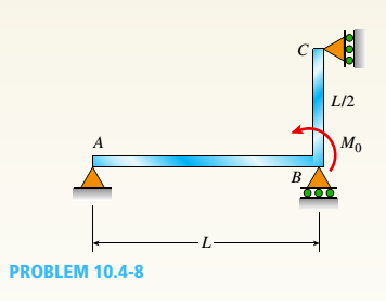
The continuous frame ABC has a pin support at /l, roller supports at B and C, and a rigid corner connection at B (see figure). Members AB and BC each have flexural rigidity EI. A moment M0acts counterclockwise at B, Note: Disregard axial deformations in member AB and consider only the effects of bending.
- Find all reactions of the frame.
Find the required new length of member BC in terms of L., so that
Expert Solution & Answer
Want to see the full answer?
Check out a sample textbook solution
Chapter 10 Solutions
Mechanics of Materials (MindTap Course List)
Ch. 10 - A propped cantilever steel beam is constructed...Ch. 10 - A fixed-end b earn is subjected to a point load at...Ch. 10 - A propped cantilever beam AB of a length L is...Ch. 10 - A fixed-end beam AB of a length L supports a...Ch. 10 - A cantilever beam AB of a length L has a fixed...Ch. 10 - A cantilever beam of a length L and loaded by a...Ch. 10 - A cantilever beam has a length L and is loaded by...Ch. 10 - A propped cantilever beam of a length L is loaded...Ch. 10 - A propped cantilever beam of a length L is loaded...Ch. 10 - A fixed-end beam of a length L is loaded by a...
Ch. 10 - A fixed-end b earn of a length L is loaded by a...Ch. 10 - A fixed-end beam of a length L is loaded by...Ch. 10 - A counterclockwise moment M0acts at the midpoint...Ch. 10 - A propped cantilever beam of a length L is loaded...Ch. 10 - A propped cantilever beam is subjected to uniform...Ch. 10 - Repeat Problem 10.3-15 using L = 3.5 m, max = 3...Ch. 10 - A two-span, continuous wood girder (E = 1700 ksi)...Ch. 10 - A fixed-end beam AB carries point load P acting at...Ch. 10 - A fixed-end beam AB supports a uniform load of...Ch. 10 - -4-4 A cantilever beam is supported at B by cable...Ch. 10 - A propped cantilever beam AB of a length L carries...Ch. 10 - A beam with a sliding support at B is loaded by a...Ch. 10 - A propped cantilever beam of a length 2L with a...Ch. 10 - The continuous frame ABC has a pin support at /l,...Ch. 10 - The continuous frame ABC has a pin support at A,...Ch. 10 - Beam AB has a pin support at A and a roller...Ch. 10 - The continuous frame ABCD has a pin support at B:...Ch. 10 - Two flat beams AB and CD, lying in horizontal...Ch. 10 - -4-13 A propped cantilever beam of a length 2L is...Ch. 10 - A propped cantilever beam of a length 2L is loaded...Ch. 10 - Determine the fixed-end moments (MAand MB) and...Ch. 10 - A continuous beam ABC wit h two unequal spans, one...Ch. 10 - Beam ABC is fixed at support A and rests (at point...Ch. 10 - A propped cantilever beam has flexural rigidity EI...Ch. 10 - A triangularly distributed 1oad with a maximum...Ch. 10 - A fixed-end beam is loaded by a uniform load q =...Ch. 10 - Uniform load q = 10 lb/ft acts over part of the...Ch. 10 - A propped cantilever beam with a length L = 4 m is...Ch. 10 - A cant i levé r b ea m i s supported by a tie rod...Ch. 10 - The figure shows a nonprismatic, propped...Ch. 10 - A beam ABC is fixed at end A and supported by beam...Ch. 10 - A three-span continuous beam A BCD with three...Ch. 10 - A beam rests on supports at A and B and is loaded...Ch. 10 - A propped cantilever beam is subjected to two...Ch. 10 - A propped cantilever beam is loaded by a...Ch. 10 - A fixed-end beam AB of a length L is subjected to...Ch. 10 - A temporary wood flume serving as a channel for...Ch. 10 - Two identical, simply supported beams AB and CD...Ch. 10 - The cantilever beam AB shown in the figure is an...Ch. 10 - The beam AB shown in the figure is simply...Ch. 10 - The continuous frame ABC has a fixed support at A,...Ch. 10 - The continuous frame ABC has a pinned support at...Ch. 10 - A wide-flange beam ABC rests on three identical...Ch. 10 - A fixed-end beam AB of a length L is subjected to...Ch. 10 - A beam supporting a uniform load of intensity q...Ch. 10 - A thin steel beam AB used in conjunction with an...Ch. 10 - Find an expression for required moment MA(in terms...Ch. 10 - Repeat Problem 10.4-41 for the loading shown in...Ch. 10 - A propped cantilever beam is loaded by two...Ch. 10 - A cable CD of a length H is attached to the third...Ch. 10 - A propped cantilever beam, fixed at the left-hand...Ch. 10 - Solve t he preceding problem by integrating the...Ch. 10 - A two-span beam with spans of lengths L and L/3 is...Ch. 10 - Solve the preceding problem by integrating the...Ch. 10 - Assume that the deflected shape of a beam AB with...Ch. 10 - (a) A simple beam AB with length L and height h...
Knowledge Booster


Learn more about
Need a deep-dive on the concept behind this application? Look no further. Learn more about this topic, mechanical-engineering and related others by exploring similar questions and additional content below.Similar questions
- Beam A BCD has a sliding support at A, roller supports at C and A and a pin connection at B (see figure). Assume that the beam has a rectangular cross section (b = 4 in., h = 12 in.). Uniform load q acts on ABC and a concentrated moment is applied at D. Let load variable q = 1750 lb/ft, and assume that dimension variable L = 4 ft. First, use statics to confirm the reaction moment at A and the reaction forces at Cand A as given in the figure. Then find the ratio of the magnitudes of the principal stresses (crj/os) just left of support Cat a distance d = 8 in. up from the bottom,arrow_forwardBeam A BCD has a sliding support at A, roller supports at C and A and a pin connection at B (see figure). Assume that the beam has a rectangular cross section (b = 4 in., h = 12 in.). Uniform load q acts on ABC and a concentrated moment is applied at D. Let load variable q = 1750 lb/ft, and assume that dimension variable L = 4 ft. First, use statics to confirm the reaction moment at A and the reaction forces at C and A as given in the figure. Then find the ratio of the magnitudes of the principal stresses (crj/os) just left of support Cat a distance d = 8 in. up from the bottom, The pedal and crank are in a horizontal plane and points A and B are located on the top of the crank. The load P = 160 lb acts in the vertical direction and the distances (in the horizontal plane) between the line of action of the load and points A and B are b\ = 5.0 in., h-, = 2.5 in., and/>3 = 1.0 in. Assume that the crank has a solid circular cross section with diameter d = 0.6 inarrow_forwardFind support reactions at A and D and then calculate the axial force N. shear force 1 and bending moment 11 at mid-span of column BD. Let L = 4 m, q0 = 160N/m, P = 200N, and M0= 380 N .m.arrow_forward
- Solve the preceding problem for a cantilever beam with data as b = 4 in., h = 9 in., L = 10 ft, P = 325 lb, and x = 45°.arrow_forwardThe continuous frame ABC has a pinned support at A, a sliding support at C, and a rigid corner connection at B (see figure). Members AB and BC each have length L and flexural rigidity EI. A horizontal force P acts at mid-height of member AB. Find all reactions of the frame. What is the largest bending moment Mmaxin the frame? Note: Disregard axial deformations in members AB and BC and consider only the effects of bending.arrow_forwardSolve the preceding problem using a W 310 x 129 section, L = 1.8 m, P = 9.5 kN, and or x= 60°. See Table F-l(b) of Appendix F For the dimensions and properties of the beam.arrow_forward
- Frame ABCD carries two concentrated loads (2P at T and P at ZX see figure) and also a linearly varying distributed load on AB, Find expressions for shear force Fand moment A/at x = L/3 of beam AB in terms of peak load intensity q0, force P, and beam length variable L. Let q0= P/L.arrow_forwardA cantilever beam of W 12 × 14 section and length L = 9 ft supports a slightly inclined load P = 500 lb at the free end (see figure). Plot a graph of the stress o 4at point A as a function of the angle of inclination or Plot a graph of the angle L/3, which locates the neutral axis ma as a function of the angle a. (When plotting the graphs, let a vary from 0 to 10º) See Table F-1(a) of Appendix F for the dimensions and properties of the beam.arrow_forwardSegments A B and BCD of beam A BCD are pin connected at x = 4 m. The beam is supported by a sliding support at A and roller supports at C and D (see figure). A triangularly distributed load with peak intensity of SO N/m acts on EC. A concentrated moment is applied at joint D. (a) Find reactions at supports A, C, and D. (b) Find internal stress resultants N, Y, and Mat x = 5m. (c) Repeat parts (a) and (b) for die case of the roller support at C replaced by a linear spring of stiffness kr™ 200 kN/m (see figure).arrow_forward
- Find support reactions at A and D and then calculate the axial force N, shear force V, and bending moment M at mid-span of AB. Let L = 14 ft, q0 = 12 lb/ft, P = 50 lb. and = 300 lb-ft.arrow_forwardA compound beam (see figure) has an shear release just to the left of C and a moment release just to the right of C. A plot of the moment diagram is provided below the beam for applied load P at B and triangular distributed loads v(x) on segments Z/C and CD. First, solve for reactions using statics; then plot axial force (A) and shear force (K) diagrams. Confirm that the moment diagram is that shown below. Label all critical N, V, and M values and also the distance to points where N, V, and/or M are zero.arrow_forwardA foot bridge on a hiking trail is constructed using two timber logs each having a diameter d = 0.5 m (see figure a). The bridge is simply supported and has a length L = 4 m. The top of each log is trimmed to form the walking surface (see Fig, b)LA simplified model of the bridge is shown in Fig. g. Each log must carry its own weight w = 1.2 kN/m and the weight (P = 850 N) of a person at mid-span, (see Fig. b). Determine the maximum tensile and compressive stresses in the beam (Fig, b) due to bending. If load h is unchanged, find the maximum permissible value of load ... if the allowable normal stress in tension and compression is 2.5 M Pa.arrow_forward
arrow_back_ios
SEE MORE QUESTIONS
arrow_forward_ios
Recommended textbooks for you
 Mechanics of Materials (MindTap Course List)Mechanical EngineeringISBN:9781337093347Author:Barry J. Goodno, James M. GerePublisher:Cengage Learning
Mechanics of Materials (MindTap Course List)
Mechanical Engineering
ISBN:9781337093347
Author:Barry J. Goodno, James M. Gere
Publisher:Cengage Learning
Everything About TRANSVERSE SHEAR in 10 Minutes!! - Mechanics of Materials; Author: Less Boring Lectures;https://www.youtube.com/watch?v=4x0E9yvzfCM;License: Standard Youtube License