
Mechanics of Materials (MindTap Course List)
9th Edition
ISBN: 9781337093347
Author: Barry J. Goodno, James M. Gere
Publisher: Cengage Learning
expand_more
expand_more
format_list_bulleted
Concept explainers
Videos
Textbook Question
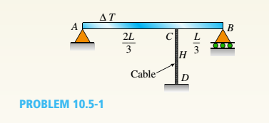
Chapter 10, Problem 10.5.1P
A cable CD of a length H is attached to the third point of a simple beam AB of a length L (see figure). The moment of inertia of the beam is I, and the effective cross-sectional area of the cable is A. The cable is initially taut but without any initial tension,
(a)
Obtain a formula for the tensile force S in the
cable when the temperature drops uniformly by
(b)
Repeat part (a), assuming a wood beam and
steel cable.
Expert Solution & Answer

Trending nowThis is a popular solution!

Students have asked these similar questions
The beam in the figure below is subjected to a load P = 3.5 kN at its end. Young’s modulus is 210 GPa and the moment of inertia for the beam’s cross-section is 5×106 mm4.
If a = 1.5 m and b = 0.6 m, determine:
a) Reaction value at support A. Positive direction is considered upwards.
b) moment equation M(x1) in the segment AB, where x1 changes from 0 at support A to a at support B. Enter the equation in terms of variables P, a, band x1.
c) moment equation M(x2) in the segment BC, where x2 changes from 0 at point C to b at support B. Enter the equation in terms of variables P, a, band x2.
d) the value of the constant of integration C1
e) the value of the constant of integration C2
f) the value of the constant of integration C3
g) the value of the constant of integration C4
h) the value of displacement at point C
i) the position of maximum displacement in the segment AB
j) the value of maximum displacement in the segment AB
The beam shown in the figure is made of material with a tensile strength of 24 MPa. Accordingly, determine the maximum moment (Nm) that can be applied to the beam.
A vertical load P is applied at the center B of the upper
section of a homogeneous frustum of a circular cone of length L, minimum
radius rB, and maximum radius rA, as shown in the figure below. It is
made of a material with a modulus of elasticity E. Neglect the effect of
its weight. Use the following values: rA = 2 in, rB = 0.5 in, L = 3 ft,
E = 30 (103
) ksi, and P = 1800 lbf. Discretize the original geometry into
three equal-length finite elements and
(a) Compute all the nodal displacements.
(b) Compute all the element axial stresses.
(c) Plot the displacement field from the finite element method solution.
(d) Plot the axial stress field from the finite element method solution.
Chapter 10 Solutions
Mechanics of Materials (MindTap Course List)
Ch. 10 - A propped cantilever steel beam is constructed...Ch. 10 - A fixed-end b earn is subjected to a point load at...Ch. 10 - A propped cantilever beam AB of a length L is...Ch. 10 - A fixed-end beam AB of a length L supports a...Ch. 10 - A cantilever beam AB of a length L has a fixed...Ch. 10 - A cantilever beam of a length L and loaded by a...Ch. 10 - A cantilever beam has a length L and is loaded by...Ch. 10 - A propped cantilever beam of a length L is loaded...Ch. 10 - A propped cantilever beam of a length L is loaded...Ch. 10 - A fixed-end beam of a length L is loaded by a...
Ch. 10 - A fixed-end b earn of a length L is loaded by a...Ch. 10 - A fixed-end beam of a length L is loaded by...Ch. 10 - A counterclockwise moment M0acts at the midpoint...Ch. 10 - A propped cantilever beam of a length L is loaded...Ch. 10 - A propped cantilever beam is subjected to uniform...Ch. 10 - Repeat Problem 10.3-15 using L = 3.5 m, max = 3...Ch. 10 - A two-span, continuous wood girder (E = 1700 ksi)...Ch. 10 - A fixed-end beam AB carries point load P acting at...Ch. 10 - A fixed-end beam AB supports a uniform load of...Ch. 10 - -4-4 A cantilever beam is supported at B by cable...Ch. 10 - A propped cantilever beam AB of a length L carries...Ch. 10 - A beam with a sliding support at B is loaded by a...Ch. 10 - A propped cantilever beam of a length 2L with a...Ch. 10 - The continuous frame ABC has a pin support at /l,...Ch. 10 - The continuous frame ABC has a pin support at A,...Ch. 10 - Beam AB has a pin support at A and a roller...Ch. 10 - The continuous frame ABCD has a pin support at B:...Ch. 10 - Two flat beams AB and CD, lying in horizontal...Ch. 10 - -4-13 A propped cantilever beam of a length 2L is...Ch. 10 - A propped cantilever beam of a length 2L is loaded...Ch. 10 - Determine the fixed-end moments (MAand MB) and...Ch. 10 - A continuous beam ABC wit h two unequal spans, one...Ch. 10 - Beam ABC is fixed at support A and rests (at point...Ch. 10 - A propped cantilever beam has flexural rigidity EI...Ch. 10 - A triangularly distributed 1oad with a maximum...Ch. 10 - A fixed-end beam is loaded by a uniform load q =...Ch. 10 - Uniform load q = 10 lb/ft acts over part of the...Ch. 10 - A propped cantilever beam with a length L = 4 m is...Ch. 10 - A cant i levé r b ea m i s supported by a tie rod...Ch. 10 - The figure shows a nonprismatic, propped...Ch. 10 - A beam ABC is fixed at end A and supported by beam...Ch. 10 - A three-span continuous beam A BCD with three...Ch. 10 - A beam rests on supports at A and B and is loaded...Ch. 10 - A propped cantilever beam is subjected to two...Ch. 10 - A propped cantilever beam is loaded by a...Ch. 10 - A fixed-end beam AB of a length L is subjected to...Ch. 10 - A temporary wood flume serving as a channel for...Ch. 10 - Two identical, simply supported beams AB and CD...Ch. 10 - The cantilever beam AB shown in the figure is an...Ch. 10 - The beam AB shown in the figure is simply...Ch. 10 - The continuous frame ABC has a fixed support at A,...Ch. 10 - The continuous frame ABC has a pinned support at...Ch. 10 - A wide-flange beam ABC rests on three identical...Ch. 10 - A fixed-end beam AB of a length L is subjected to...Ch. 10 - A beam supporting a uniform load of intensity q...Ch. 10 - A thin steel beam AB used in conjunction with an...Ch. 10 - Find an expression for required moment MA(in terms...Ch. 10 - Repeat Problem 10.4-41 for the loading shown in...Ch. 10 - A propped cantilever beam is loaded by two...Ch. 10 - A cable CD of a length H is attached to the third...Ch. 10 - A propped cantilever beam, fixed at the left-hand...Ch. 10 - Solve t he preceding problem by integrating the...Ch. 10 - A two-span beam with spans of lengths L and L/3 is...Ch. 10 - Solve the preceding problem by integrating the...Ch. 10 - Assume that the deflected shape of a beam AB with...Ch. 10 - (a) A simple beam AB with length L and height h...
Knowledge Booster


Learn more about
Need a deep-dive on the concept behind this application? Look no further. Learn more about this topic, mechanical-engineering and related others by exploring similar questions and additional content below.Similar questions
- A sliding collar of weight W = 150 lb falls From a height h = 2.0 in. onto a flange at the bottom of a slender vertical rod (see figure). The rod has a length L = 4.0 ft, cross-sectional area A = 0.75 in2, and modulus of elasticity E = 30 X 106 psi. Calculate the following quantities: (a) the maximum downward displacement of the flange, (b) the maximum tensile stress in the rod, and (c) the impact factor.arrow_forwardA sandwich beam having steel faces enclosing a plastic core is subjected to a bending moment M = 5 kN · m. The thickness of each steel face is 1 = 3 mm with modulus of elasticity E = 200 GPa, The height of the plastic core is hp= 140 mm, and its modulus of elasticity is Ep= 800 MPa. The overall dimensions of the beam are h = 146 mm and h = 175 mm. Using the transformed-section method, determine the maximum tensile and compressive stresses in the faces and the core.arrow_forwardThe cross section of a beam made of thin strips of aluminum separated by a lightweight plastic is shown in the figure. The beam has width b = 3.0 in., the aluminum strips have thickness t = 0.1 in., and the plastic segments have heights d = 1.2 in. and 3d = 3.6 in. The total height of the beam is h = 6.4 in. The moduli of elasticity for the aluminum and plastic are EM= 11 X 106 psi and Ep= 440 X 10* psi, respectively. Determine the maximum stresses trAiand pin the aluminum and plastic, respectively, due to a bending moment of 6,0 kip-in.arrow_forward
- *16 A prismatic bar AB of length L, cross-sectional area A, modulus of elasticity E, and weight Changs vertically under its own weight (see figure). (a) Derive a formula for the downward displacement Scof point E. located at distance It from the lower end of the bar. (b) What is the elongation SBof the entire bar? (c) What is the ratio £ of the elongation, of the upper half of the bar to the elongation of the lower half of the bar? (d) If bar A B is a riser pipe hanging from a drill rig at sea. what is the total elongation of the pipe? Let L = 1500 m, A - 0.ol57 m2, and E = 210 GPa. See Appendix 1 for weight densities of steel and sea water. (See Probs. 1.4-2 and J.7-13 for additional figures.)arrow_forwardTwo pipe columns (AB, FC) are pin-connected to a rigid beam (BCD), as shown in the figure. Each pipe column has a modulus of E, but heights (L1or L2) and outer diameters (d1or different for each column. Assume the inner diameter of each column is 3/4 of outer diameter. Uniformly distributed downward load q = 2PIL is applied over a distance of 3L/4 along BC, and concentrated load PIA is applied downward at D. (a) Derive a formula for the displacementarrow_forwardA weight W = 4500 lb falls from a height h onto a vertical wood pole having length L = 15 ft, diameter d = 12 in., and modulus of elasticity E = 1.6 × 10⁶ psi (see figure). If the allowable stress in the wood under an impact load is 2500 psi. what is the maximum permissible height h?arrow_forward
- A prismatic bar AD of length L, cross-sectional area A. and modulus of elasticity E is subjected to loads 5P, 3P, and P acting at points B, C, and D, respectively (see figure). Segments AB, BC, and CD have lengths L/6, L/2, and L/3, respectively. (a) Obtain a formula for the strain energy U of the bar. (b) Calculate the strain energy if P = 6 kips, L = 52 in., A = 2.76 in2, and the material is aluminum with E = 10.4 × 10⁶ psi.arrow_forwardThe beam ABC shown in the figure is simply supported at A and B and has an overhang from B to C. The loads consist of a horizontal force P1= 4,0 kN acting at the end of a vertical arm and a vertical force P2= 8.0 kN acting at the end of the overhang, Determine the shear force Fand bending moment M at a cross section located 3,0 m from the left-hand support. Note: Disregard the widths of the beam and vertical arm and use centerline dimensions when making calculations, Find the value of load A that results in V = 0 at a cross section located 2.0 m from the left-hand support. If P2= 8.0 kN, find the value of load P1that results in M = 0 at a cross section located 2,0 m from the left-hand support.arrow_forwardA beam of square cross section (a = length of each side) is bent in the plane of a diagonal (see figure). By removing a small amount of material at the top and bottom corners, as shown by the shaded triangles in the figure, you can increase the section modulus and obtain a stronger beam, even though the area of the cross section is reduced. Determine the ratio ß defining the areas that should be removed in order to obtain the strongest cross section in bending. By what percent is the section modulus increased when the areas arc removed?arrow_forward
- A beam is constructed using two angle sections (L 102 × 76 × 6.4) arranged back to back, as shown in the figure. The beam is fixed al joint A and attached to an elastic support having a spring constant k = l750 kN/m al joint B. Assume only the beam is subjected to temperature increase AT = 45°C. Calculate the thermal stress developed in the beam and the displacement at point B. Assume that a = 12 X 10-6/?. Let E = 205 GPaarrow_forwardThe L-shaped arm ABCD shown in the figure lies in a vertical plane and pivots about a horizontal pin at A. The arm has a constant cross-sectional area and total weight W. A vertical spring of stiffness k supports the arm at point B. (a) Obtain a formula for the elongation of the spring due to the weight of the arm. (b) Repeat part (a) if the pin support at A is moved to D.arrow_forwardA wood beam with cross-sectional dimensions 200 mm x 300 mm is reinforced on its sides by steel plates 12 mm thick (see figure). The moduli of elasticity for the steel and wood are E±= 190 GPa and Ew= 11 GPa, respectively. Also, the corresponding allowable stresses are eS= 110 MPa and ew = 7.5 MPa, (a) Calculate the maximum permissible bending moment Mmaxwhen the beam is bent about the- axis. Repeat part (a) if the beam is now bent about its y axis. Find the required thickness of the steel plates on the beam bent about the y axis so that Mmaxis the same for both beam orientations.arrow_forward
arrow_back_ios
SEE MORE QUESTIONS
arrow_forward_ios
Recommended textbooks for you
 Mechanics of Materials (MindTap Course List)Mechanical EngineeringISBN:9781337093347Author:Barry J. Goodno, James M. GerePublisher:Cengage Learning
Mechanics of Materials (MindTap Course List)
Mechanical Engineering
ISBN:9781337093347
Author:Barry J. Goodno, James M. Gere
Publisher:Cengage Learning
Everything About COMBINED LOADING in 10 Minutes! Mechanics of Materials; Author: Less Boring Lectures;https://www.youtube.com/watch?v=N-PlI900hSg;License: Standard youtube license