
Concept explainers
Videos
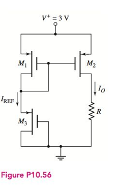
The circuit in Figure P 10.56 is a PMOS version of a two-transistor MOScurrent mirror. Assume transistor parameters of
(a)
The value of
Answer to Problem 10.56P
Explanation of Solution
Given:
The circuit parameters are
The transistor parameters are
Calculation:
The given circuit is
The transistor
Now,
Put the value of
From equation (2) and (3),
Now the reference current will be
Now calculate output current by using aspect ratio.
Conclusion:
(b)
The largest value of
Answer to Problem 10.56P
Explanation of Solution
Given:
The circuit parameters are
The transistor parameters are
Calculation:
The given circuit is

The transistor
Now,
Put the value of
From equation (2) and(3),
Now the reference current will be
Now calculate output current by using aspect ratio.
Calculate the largest value of R when
According to Ohm’s law,
Also,
From equation (4) and (5),
Conclusion:
Want to see more full solutions like this?
Chapter 10 Solutions
Microelectronics: Circuit Analysis and Design


- 2. The output stage of a transmitter requires, owing to supply voltage limitations, a downward impedance transformation of the antenna resistance. The load impedance is 50-Ω. Suppose we wish to deliver 3 Watts of power into such a load at 915 MHz, but the power amplifier has a maximum peak-to-peak sinusoidal voltage of only 7 Volts because of various losses and transistor breakdown problems. Design a two section L-match of low pass type to allow that 3 Watts to be delivered to the 50-Ω load. Assume that all reactive elements are ideal.arrow_forwardThe quality factor for the TE101 mode in a hollow rectangular resonator is given as; What should be the size of the resonator so that the quality factor of a hollow cubic resonator made of a conductor with a skin thickness of 0.50 nm is 25,000?arrow_forwardIdentify how the excessive bandwidth use of FM can be overcome. (Check all that apply.) By using narrowband FM with small deviation ratios By using wideband FM with large deviation ratios By operating in the ultrahigh frequency (UHF) region By operating in the ultralow frequency (ULF) region By operating in the microwave regionarrow_forward
- Regarding phase modulation (PM), an increase in the PM index, µ, results in an increase in the modulated signal’s bandwidth. (Explain) True Falsearrow_forwardFor a square modulating signal with value 0 and 3 V entering an FM modulator with drift sensitivity of 0.1KHz / V and a carrier frequency of 100KHz with Vc = 5V, draw the waveform of the resulting modulated signal indicating the frequency and amplitude values of the wave.arrow_forwardAnswer the question: For a QPSK modulator with an input data rate (fb) equal to 10 Mbps and a carrier frequency of 70 MHz, determine the minimum double-sided Nyquist bandwidth (fN) , the highest fundamental signal, and the baud rate.arrow_forward
- How many channels are available in the 2.4 GHz band? List all the channels. What is the channelbandwidth?arrow_forwardA power spectral density has a roughly Gaussian shape for which the mean is at 1000Hz and the standard deviation of the distribution is 10 Hz. Bearing in mind what we know about the Gaussian distribution, estimate the amount of power that lies in the region that is in EXCESS of 1020Hz, if the TOTAL power in the signal is 10 Watts.arrow_forward-MCQ- FM modulator is used to transmit a cosine message signal with 4V amplitude and 20Hz frequency. The frequency deviation constant kf = 25 Hz/V, the carrier is a cosine sign with an amplitude of 10V and a frequency of 2000Hz. The FM modulated signal is passed through a bandpass filter and 90% of the power of the modulated signal remains. What is the bandwidth of the FM modulated signal in this case? a) 240hz b) 20hz c) 100hz d)200hzarrow_forward
- What are the relative amplitudes of the fourth pair of sidebands for an FM signal with a deviation ratio of 8?arrow_forwardConsider a modulating signal of 20khz that is applied to an FM modulator, whose modulation index (β) is a value of 4, then the real bandwidth will be:arrow_forwardWhat is the typical response time for MOV's?arrow_forward
 Introductory Circuit Analysis (13th Edition)Electrical EngineeringISBN:9780133923605Author:Robert L. BoylestadPublisher:PEARSON
 Delmar's Standard Textbook Of ElectricityElectrical EngineeringISBN:9781337900348Author:Stephen L. HermanPublisher:Cengage Learning
 Programmable Logic ControllersElectrical EngineeringISBN:9780073373843Author:Frank D. PetruzellaPublisher:McGraw-Hill Education
 Fundamentals of Electric CircuitsElectrical EngineeringISBN:9780078028229Author:Charles K Alexander, Matthew SadikuPublisher:McGraw-Hill Education
 Electric Circuits. (11th Edition)Electrical EngineeringISBN:9780134746968Author:James W. Nilsson, Susan RiedelPublisher:PEARSON
 Engineering ElectromagneticsElectrical EngineeringISBN:9780078028151Author:Hayt, William H. (william Hart), Jr, BUCK, John A.Publisher:Mcgraw-hill Education,