
Videos
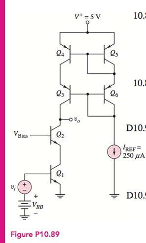
A BJT cascode amplifier with a cascode active load is shown inFigure P10.89. Assume transistor parameters of
The small-signal voltage gain
Answer to Problem 10.89P
Explanation of Solution
Given:
Calculation:
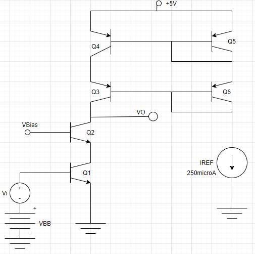
The given circuit is,
The equivalent circuit for active load amplifier is as shown,
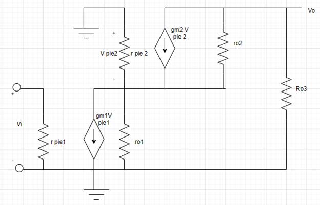
The expression for input voltage
Now expression for output resistance is,
Put equation (3) in equation (2)
Consider
Now expression for hybrid resistor parameter.
Now output voltage will be,
Consider
Put value from equation (8) to equation (6)
Put
Now
Substitute the value for
Now
Substitute the derived values in equation (10)
Conclusion:
Want to see more full solutions like this?
Chapter 10 Solutions
Microelectronics: Circuit Analysis and Design


- (a) Does the MOSFET as shown remain in the active region of operation during the full-output signal swing? (b) If the dc drain current of the MOSFET in the active region is given by ID = (Kn/2)(VGS − VTN)2, what are the values of the parameter Kn and threshold voltage VTN for the transistor shown? (c) Express the amplifier voltage given in dB.arrow_forwardIn the above circuit, BJT's VT values are not identical. a) For the collector currents of transistors to be 2 mA What should the R0 value be? b) Find the values for gm1 and gm2. c) Find the differential mode gain (ADM). d) Find the common mode gain (ACM). e) Find the CMRR value.arrow_forwardDiscuss and explain all capacitive reactances present in a BJT amplifier when frequency of the input signal isoutside of Midrange Region.arrow_forward
- Suppose the tail current source is implemented using another transistor with the same BJT parameters, what would be the common-mode input range of this amplifier? Where V2>= VCM>=V1. Determine V1 and V2.arrow_forwardThe common-emitter amplifier given in the figure in the circuit, Vcc=9V, R1=27kΩ, R2=15kΩ, RE=1.2kΩ and RC=2.2kΩ. Transistor β=100 has value. a-) If it has values of Rsig=10kΩ and RL=2kΩ Calculate the IE of the amplifier. b-) For small signal analysis of transistor Find the value of Rin by deriving the π-model c-) Calculate vo/vsig and io/ii.arrow_forward(a) What are the Q-points for the transistors in the amplifier as shown if VCC = 15 V, VEE = 15 V, IEE = 400 μA, βF = 100, REE = 270 kΩ,RC =47 kΩ, VA=∞, and βF =100? (b) What are the differential-mode gain, common-mode gain, CMRR, and differential-mode and common-modeinput and output resistances? (c) Repeat part (b) for VA = 50 V.arrow_forward
- Enclosed please find an amplifier circuit designed with a BJT transistor. VCC = 9Volt for the circuit. All capacity values are selected sufficiently large. BJT Transistor B = 100 Vbe(on) = 0.8V, VA=100V, Vt= 26mV Vce (sat) = 0.15Volt. Calculate “Vceq” and “Icq “ values at the operating point of the circuit. In what area does this BJT transistor work in? Draw the small signal equivalent circuit of the circuit. Calculate the AC small signal current earnings of the circuit (Ai = I out / I input). Note: Is the current passes over Rs source resistance and The IO current passes over RL source resistance. Please Calculate Rin input resistance?arrow_forwardGiven the circuit of Figure P10.3, determine theoperating point of the transistor. Assume the BJT is a silicon device with β = 100. In what region is the transistor?arrow_forwardIf RF = 50kΩ, R1 = 500kΩ and signal input is 15mV peak in a non-inverting operational amplifier, what will be the Vout value?arrow_forward
- What type of bias circuit can be used for the BJT amplifiers? Can the same type of bias circuit be configured as different types of BJT amplifier? Briefly answer.arrow_forwardWhat is the effect of the bypass capacitor value on the overall amplifier gain? what looks like the frequency response of the BJT amplifier What is the effect of the coupling (series) resistor values on the frequency response?arrow_forward(a) What are the Q-points for the transistors in the amplifier as shown if VDD = 9 V, VSS = 9 V, ISS = 40 μA, RSS = 1.25 MΩ, and RD = 300 kΩ? Assume Kp = 200 μA/V2, γ = 0.6 V0.5, 2φF = 0.6 V, and VTO = −1 V. (b) What are the differential-mode gain, common-mode gain, CMRR, and differential-mode and common-mode input resistances?arrow_forward
 Introductory Circuit Analysis (13th Edition)Electrical EngineeringISBN:9780133923605Author:Robert L. BoylestadPublisher:PEARSON
 Delmar's Standard Textbook Of ElectricityElectrical EngineeringISBN:9781337900348Author:Stephen L. HermanPublisher:Cengage Learning
 Programmable Logic ControllersElectrical EngineeringISBN:9780073373843Author:Frank D. PetruzellaPublisher:McGraw-Hill Education
 Fundamentals of Electric CircuitsElectrical EngineeringISBN:9780078028229Author:Charles K Alexander, Matthew SadikuPublisher:McGraw-Hill Education
 Electric Circuits. (11th Edition)Electrical EngineeringISBN:9780134746968Author:James W. Nilsson, Susan RiedelPublisher:PEARSON
 Engineering ElectromagneticsElectrical EngineeringISBN:9780078028151Author:Hayt, William H. (william Hart), Jr, BUCK, John A.Publisher:Mcgraw-hill Education,