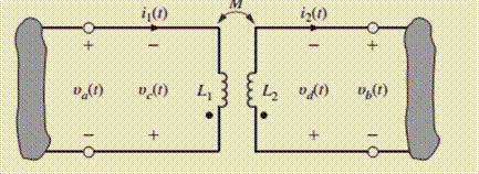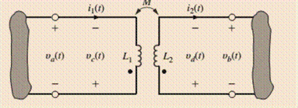
Given the network in Fig. P10.1,
(a) write the equations for
(b) write the equations for

a
The equations for
Answer to Problem 1P
The equations are:
Explanation of Solution
Given:
The given circuit is shown below.

Calculation:
Referring to the given circuit, applying the Kirchhoff’s voltage law to the left side of the loop:
From the circuit:
Solving equation 1 and 2:
Now applying the KVL to the right side of the loop:
Therefore, the equation will be:
b
The equations for
Answer to Problem 1P
The equations are:
Explanation of Solution
Given:
The given circuit is shown below.

Calculations:
From part (a), the equations of the
From the circuit:
Hence, solving the equation:
Therefore, the equations are:
Want to see more full solutions like this?
Chapter 10 Solutions
Basic Engineering Circuit Analysis
- Solve the problem. PROVIDE THE GIVEN, REQUIRED, EQUATION, SOLUTION, AND FINAL ANSWER WAO’s frequency is 85.2 MHz. What does this mean, and what period does this correspond to?arrow_forwardGiven G1(w,x,y,z) = Σm(0,1,2,3,7,8,10) + Σd(5,6,11,15). Derive the POS and SOP.arrow_forwardThe voltage (in Volts) across an element is given as v(t)= 50 cos(6ft +24.7°) whereas the current (in Amps) though the element is i(t) = - 20 sin(6ft +55°); where time, t is the time and f is the frequency in seconds and Hertz respectively. Determine the phase angle between the two harmonic functionsarrow_forward
- qq10arrow_forwardConsider RS x(t)=A cos(10 π t) + B sin(10 π t), where A and B are independent RVs, drawn from zero-mean Gaussian distribution with variance a. Find the mean and autocorrelation of x(t). Is it WSS? Find the PSD of x(t). If A and B had different variance, would x(t) be WSS?arrow_forwardThe frequency of the source voltage in the circuit isadjusted until vg is in phase with ig. What is the value of ω inradians per second?2. If ig=60 cosωt mA (where ω is the frequency found in [a]), what isthe steady-state expression for vg?arrow_forward
- Assume a mobile travelling at a velocity of 15 m/s receives two multipath components at a carrier frequency of 1260 MHz. The first component is assumed to arrive at with an initial phase of and a power of -73 dBm. The second component is 3 dB weaker than the first one and arrives at , also with initial phase of . If the mobile moves directly to the direction of arrival of the first component and directly away from the direction of arrival of the second component, compute the following: B) Compute the average narrowband power received over this observation interval. Hence, compare the average narrowband and wideband received powers over the interval.arrow_forwardAn interview is held with a student about the importance of education for thirty minutes at a radio station. It was later amplitude modulated & transmitted to receivers on the school campus.The expression below describes the transmitted signal a(z) a(z)= Acos(16πz) where A=3cos(10πz) a. In an expression form, express a(z) as a sum of sinusoids & determine the frequency components of the signal a(z)b. To adequately & fully recover the signal at the receiver, determine the rate at which the signal should be sampled.c. Determine the discrete signal,a[n] that was transmitted in a reduced form & the angular frequency assuming the signal a(z) is sampled at ten Hertz.arrow_forwardA study needs to be carried out on the electrical network shown: For this study, different values of frequencies are selected from the interval 0≤ w ≤10rad / s 2.1 If in a first study w = 10rad/s is chosen, find the impedance, ZL, that must be connected between terminals a-b so that the network shown transfers the maximum average power.2.2 Determine the value of the maximum power referred to in the previous paragraph2.3 In a second study, the frequency w = 0 is adjusted. Will the value of the impedance found in part 2.1 change? Argue the answer numericallyarrow_forward
- A transmitter with a carrier power of 10 W at a frequency of 25 MHz operated into a 50 ohms load. It is modulated at 60% by a 2 kHz sine wave. (a) Sketch the signal in the frequency domain. Show power and frequency scales. The power scale should be in dBm. (b) What is the total signal power? (c) What is the RMS voltage of the signal?arrow_forwardDISCRETE TIME GIVEN SYSTEM.Determine the poles and zeros of this system, and show how they relate to each other.The system is only marginally stable True False Find the frequency response of this system. ( NEED NEAT HANDWRITTEN SOLUTION ONLY OTHERWISE DOWNVOTE).arrow_forwardCSE For an electronic device operating at 20°C with a bandwidth of 12 kHz, determine the thermal noise power in watts and dBm.arrow_forward
 Introductory Circuit Analysis (13th Edition)Electrical EngineeringISBN:9780133923605Author:Robert L. BoylestadPublisher:PEARSON
 Delmar's Standard Textbook Of ElectricityElectrical EngineeringISBN:9781337900348Author:Stephen L. HermanPublisher:Cengage Learning
 Programmable Logic ControllersElectrical EngineeringISBN:9780073373843Author:Frank D. PetruzellaPublisher:McGraw-Hill Education
 Fundamentals of Electric CircuitsElectrical EngineeringISBN:9780078028229Author:Charles K Alexander, Matthew SadikuPublisher:McGraw-Hill Education
 Electric Circuits. (11th Edition)Electrical EngineeringISBN:9780134746968Author:James W. Nilsson, Susan RiedelPublisher:PEARSON
 Engineering ElectromagneticsElectrical EngineeringISBN:9780078028151Author:Hayt, William H. (william Hart), Jr, BUCK, John A.Publisher:Mcgraw-hill Education,


