
Videos
Determine the individual contribution each current source makes to the two nodal voltages V1 and V2 as represented in Fig. 10.67.
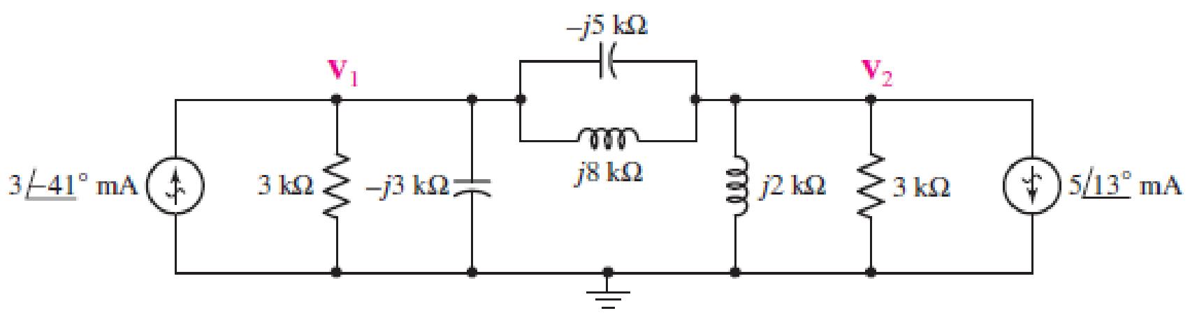
■ FIGURE 10.67
Find the expressions for nodal voltages
Answer to Problem 61E
The expressions for nodal voltages
Explanation of Solution
Calculation:
Refer to Figure in the respective question.
Case 1:
Redraw Figure, as shown in Figure 1 by making
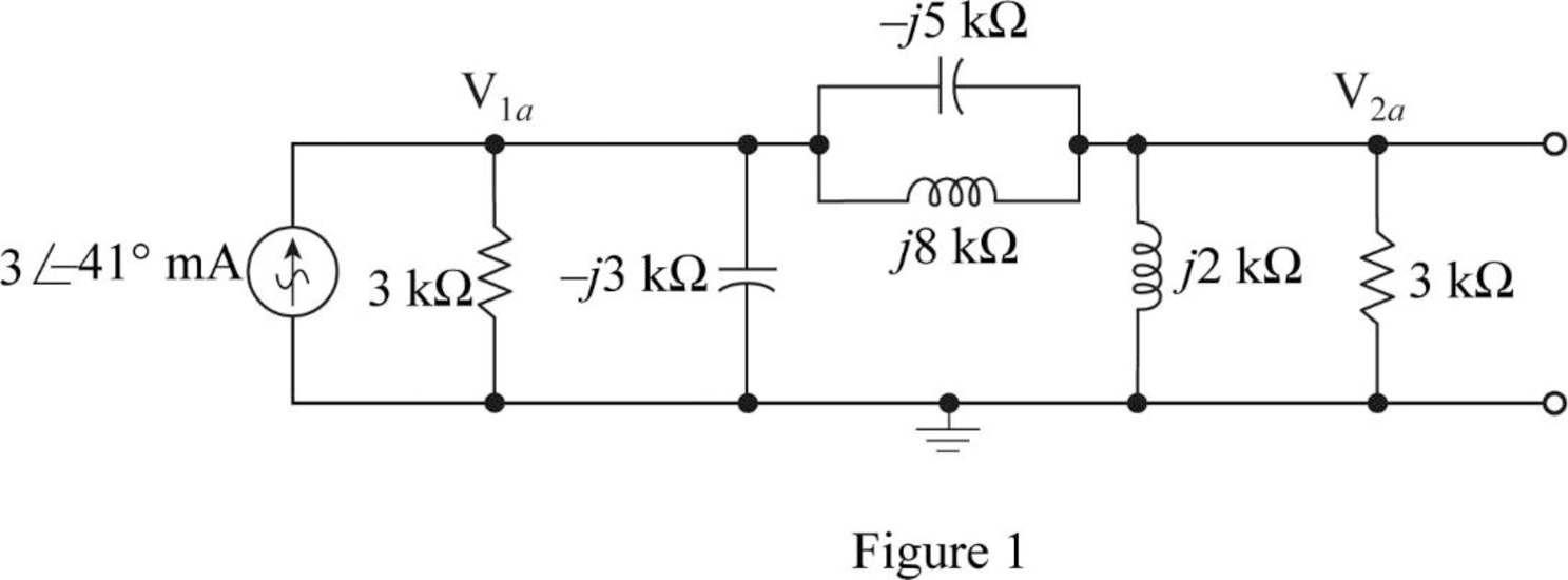
Apply KCL at node
Apply KCL at node
Write the equations (1) and (2) in matrix form.
Write the Matlab code to solve equation (3)
A = [(0.333+i*0.408) (-i*0.075); (-i*0.075) (0.333-i*0.425)];
B = [(2.264-i*1.968);(0)];
C = inv(A)*B
Matlab Output:
C =
-0.17551 - 5.58282i
0.49749 + 0.59541i
Polar equations of node voltages are as follows.
Case 2:
Redraw Figure, as shown in Figure 2 by making
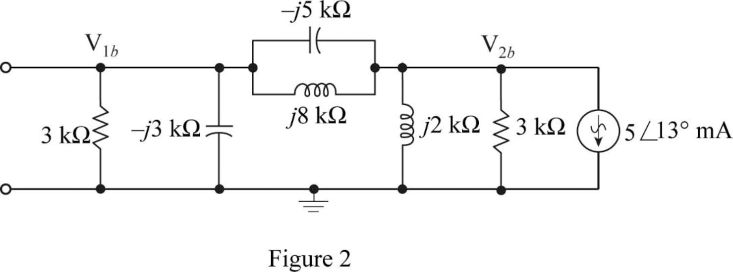
Apply KCL at node
Apply KCL at node
Write the equations (4) and (5) in matrix form.
Write the Matlab code to solve equation (6)
A = [(0.333+i*0.408) (-i*0.075); (-i*0.075) (0.333-i*0.425)];
B = [(0);(-4.87-i*1.124)];
C = inv(A)*B
Matlab Output:
C =
0.3153 - 1.2537i
-3.8514 - 8.2199i
Polar equations of node voltages are as follows.
Find nodal voltage
Substitute
Find nodal voltage
Substitute
Conclusion:
Thus, the expressions for nodal voltages
Want to see more full solutions like this?
Chapter 10 Solutions
Loose Leaf for Engineering Circuit Analysis Format: Loose-leaf


- A twin lead transmission line is embedded in a dielectric material with 3.2 relative permittivity. Its wires are separated by 2cm and their diameters are both 3mm. Compute for its characteristic impedance.arrow_forwardA PV system delivers power to a DC motor that in turn feeds a water pump. The DC motor is rated for 1.0 kW and is 85% efficient. Each PV module has 36 solar cells, arranged in a 9 x 4 matrix. The cell size is 125 mm x 125 mm and cell efficiency is 12%. Calculate the number of modules required in the array. Assume global radiation incidence normal to the panel to be 1.0 kW/m2.arrow_forwardFor the system given below, Rf=10000 ohm, Ki=0.0125 Nm/A, J=10-6 kg.m2, n=800, Kb=0.0125V/(rad/second), Ra=6.25 ohm, Ks=0.1 A/ rad, with B=0 Nm/(rad/second); Determine the K value for the 9.9% overshoot.Calculate the time of overshoot that will occur for this situation.arrow_forward
- The numerical input/output mean optical power ratio in a 1 km, length of optical fiber is found to be 2.5. Calculate the received mean optical power when a mean optical power of 1 mW is launched into a 5 km length of the fiber (assurning no joints or connectors).arrow_forward23. Calculate the reactance of a peterson coil suitable for 1 33kV, 3phase transmission system of which the capacitance to eart of each conductor is 3.2μFarrow_forwardDetermine the Norton equivalent of the circuit in Fig. 10.30 as seen from terminals a-b. Use the equivalent to find Io.arrow_forward
- Please sholve for the i hat, j hat, at k hat. Sample solutions also indicated below.arrow_forwardA receiver connected to an antenna whose resistance is 50Ω has an equivalent noise resistance of 30Ω. Calculate the equivalent noise temperature.arrow_forwardExplore the challenges and benefits of implementing power electronics-based grid solutions like STATCOM (Static Synchronous Compensator) for voltage control and stability.arrow_forward
- Calculate the velocity factor of a coaxial cable used as a transmission line with the characteristic impedance of 50 ohms; capacitance is 40 pF/m and an inductance equal to 50 microH/m.arrow_forwardA parabolic reflector antenna with a diameter of 22 meters operates at frequency of 5GHz. calculate the power gain, G (dB) of the antenna if the aperture efficiency is 50%.arrow_forwardA receiver connected to an antenna whose resistance is 50Ω has an equivalent noise resistance of 30Ω. Calculate the receiver's noise figure.arrow_forward
 Introductory Circuit Analysis (13th Edition)Electrical EngineeringISBN:9780133923605Author:Robert L. BoylestadPublisher:PEARSON
 Delmar's Standard Textbook Of ElectricityElectrical EngineeringISBN:9781337900348Author:Stephen L. HermanPublisher:Cengage Learning
 Programmable Logic ControllersElectrical EngineeringISBN:9780073373843Author:Frank D. PetruzellaPublisher:McGraw-Hill Education
 Fundamentals of Electric CircuitsElectrical EngineeringISBN:9780078028229Author:Charles K Alexander, Matthew SadikuPublisher:McGraw-Hill Education
 Electric Circuits. (11th Edition)Electrical EngineeringISBN:9780134746968Author:James W. Nilsson, Susan RiedelPublisher:PEARSON
 Engineering ElectromagneticsElectrical EngineeringISBN:9780078028151Author:Hayt, William H. (william Hart), Jr, BUCK, John A.Publisher:Mcgraw-hill Education,