
Electric Motor Control
10th Edition
ISBN: 9781133702818
Author: Herman
Publisher: CENGAGE L
expand_more
expand_more
format_list_bulleted
Videos
Textbook Question
Chapter 10, Problem 8SQ
Refer to the circuit shown in Figure 10–6. Assume that when the thermostat contact closes nothing happens. Which of the following could NOT cause this condition?
a. The high-pressure switch is open.
b. The CCOL contact is open.
c. The low-pressure switch is open.
d. he coil of the compressor contactor is open.
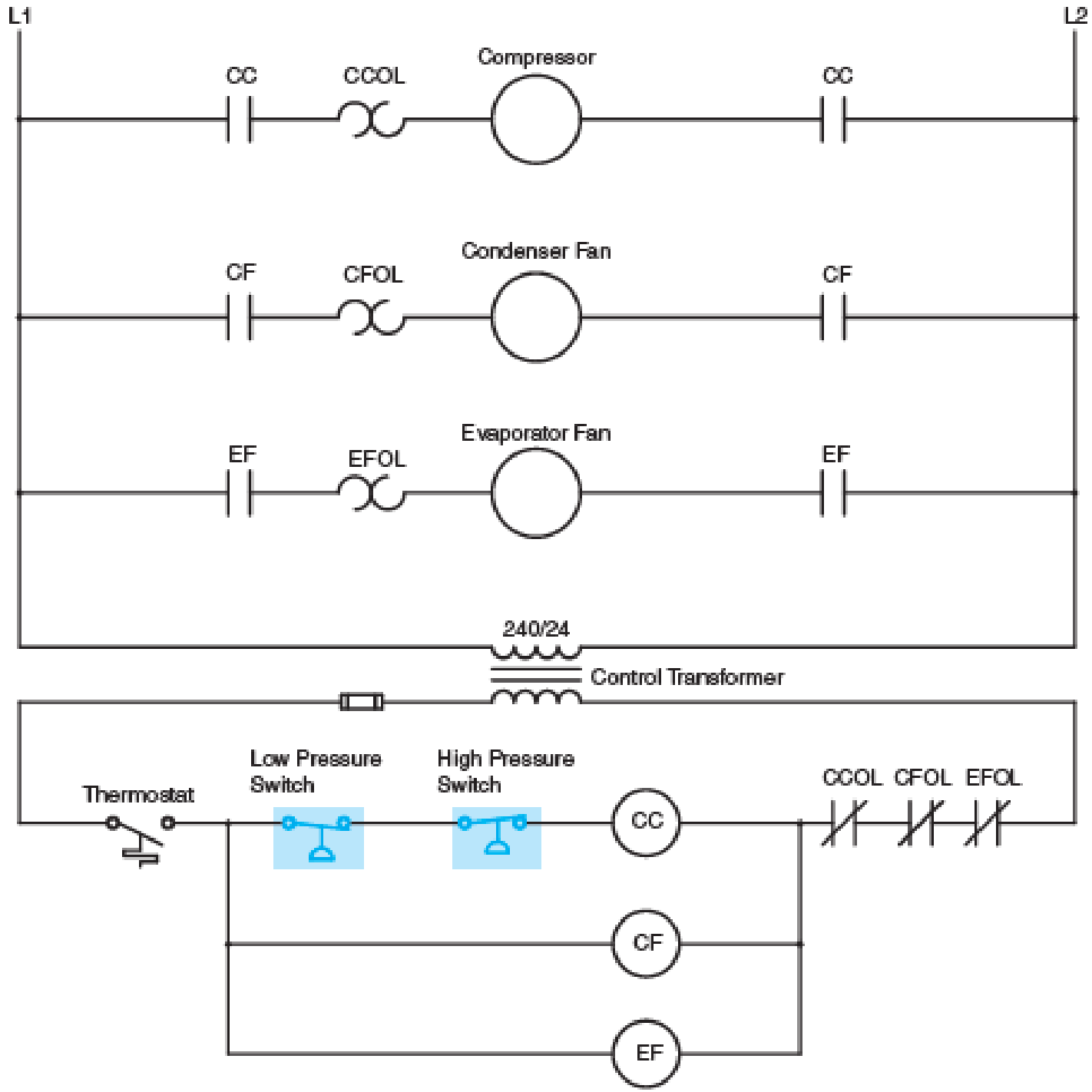
Fig. 10–6 Pressure switches are often used in air-conditioning circuits.
Expert Solution & Answer
Want to see the full answer?
Check out a sample textbook solution
Students have asked these similar questions
Question 10A-How is the minimum number of receptacle outlets determined for theliving room? What article of NEC is talking about this? B-What must be installed wherever outlets are required according to theNEC? What article of NEC is talking about this requirement?C-Which part of the NEC standard proposes the switches requirements? D-If the branch circuits supplying the receptacles in the figure at 15 A,what's the minimum size of the conductors in the branch circuit?
E-According to the AEC standard, how many outlets can a GFCI protect?
Part 2: Analysis and selection of the Wind Turbine.The team decides at install a 30 MW wind farm. The turbine that has been selected by the local contractor is an Enercon wind turbine. The specifications of all the available Enercon wind turbine is shown in the attached datasheet.
1. What are the two closed loop control systems that are used generally in wind turbines? How do they work?
2. Calculate the power density of the input power from the wind when the wind is blowing at the rated wind speed at the turbine height. Clearly show your steps in details.
the gas supply pressure to the burner is lowered and maintained at a low pressure by the?
1- air break
2- manifold
3- regulator
4- solenoid valve
Chapter 10 Solutions
Electric Motor Control
Ch. 10 - Describe how pressure switches are connected to...Ch. 10 - What type of pressure switch is generally used to...Ch. 10 - A pressure switch is set to cut in at a pressure...Ch. 10 - A pressure switch is to be installed on a system...Ch. 10 - A pressure switch is to be installed in a circuit...Ch. 10 - Refer to the circuit shown in Figure 105. If the...Ch. 10 - Refer to the circuit shown in Figure 105. Assume...Ch. 10 - Refer to the circuit shown in Figure 106. Assume...Ch. 10 - Refer to the circuit shown in Figure 106. Assume...Ch. 10 - Refer to Figure 106. When the thermostat contact...
Knowledge Booster


Learn more about
Need a deep-dive on the concept behind this application? Look no further. Learn more about this topic, electrical-engineering and related others by exploring similar questions and additional content below.Similar questions
- Refer to Figure 106. When the thermostat contact closes, the compressor and evaporator fan start but the condenser fan does not start. Which of the following could NOT cause this problem? a. The condenser fan motor is burned out. b. The coil of the CF contactor is open. c. One of the CF load contacts is defective. d. The CFOL contact is open. Fig. 106 Pressure switches are often used in air-conditioning circuits.arrow_forwardRefer to the circuit shown in Figure 106. Assume that when the thermostat contact closes the compressor does not start, but the condenser fan and evaporator fan do start. When troubleshooting the circuit, a voltmeter connected across the compressor contactor coil CC indicates 0 volts. A voltmeter connected across the high-pressure switch indicates 0 volts, and a voltmeter placed across the thermostat contact indicates 0 volts. When the voltmeter is connected across the low-pressure switch it indicates 24 volts. Which of the following conditions could cause this problem? a. The refrigerant pressure is too high. b. The compressor contactor coil is open. c. The refrigerant pressure is too low. d. The thermostat contact is open. Fig. 106 Pressure switches are often used in air-conditioning circuits.arrow_forwardWhich of the following is the largest electrical load in an air-conditioning or refrigeration system? evaporator fan motor condenser fan motor compressor relay coilarrow_forward
- 8.a. Which of the following most accurately describes the difference between a contactor and a starter?A. A starter contains a contactor and some additional protective circuitry.B. A starter is always mounted in an enclosure.C. A starter contains reversing contacts.D. A starter is always three-phase while a contactor may be single-phase or three-phase.8.b. The main bus in a motor control center is used toA. reduce the possibility of overload with large loads.B. enclose motors within a protective shield.C. distribute power to all starters in the center.D. reduce the voltage of the plant's supply.arrow_forwardYou are changing the starting relay on a central air-conditioning unit when you notice that the identifying mark on the compressor-run capacitor is connected to the run winding of the compressor. Should you change the capacitor connection so that the identifying mark is facing the line side or is it correct as connected? Explain your answer.arrow_forwardDesign a ladder program to run the material mixing system according to the following information: 1- When the start push button I0.0 is pressed, the pump (PUMP1 Q0.0) works for five seconds and then stops. 2- After that, the pump (PUMP2 Q0.1) runs for three seconds and then stops. 3- After that the pump (Mixer Motor Q0.2) works for 60 sec and then stops. 4- After that, the control valve (drian valve Q0.3) is opened, the pump (PUMP3 Q0.4) works for ten seconds. 5- The stop push button I0.1 is used to stop the system.arrow_forward
- A 350-HP squirrel-cage induction motor is connected to a 480-volts three-phase feeder. The nameplate lists the following: HP 350, Service factor 1.10, Full-load amps 408, NEMA Code B. The conductors are to be copper with THWN insulation, and 600:5 current transformers are used to reduce the current supplied to the overload heaters. The motor circuit is protected with dual-element time delay fuses. Determine the conductor size, overload heater size using the chart shown in Figure 34-7, the NEMA and IEC starter sizes, and the fuse size for this installation.arrow_forward29. The overload relay used to protect each motor - compressor set shall be selected to trip at NOT more than ____ of the motor-compressor rated load current. a. 125% b. 150% c. 140% d. 160%arrow_forwardTo answer the following questions refer to Figure 1210. When the thermostat contacts close the blower motor starts and the heating elements turn on normally. When the thermostat contacts open, the heating elements turn off and the blower motor stops running immediately. Which of the following could cause the problem? a. The thermostat contacts did not open. b. The flow switch contacts did not open. c. The fan thermostat contacts did not close. d. BMR coil is open. FIG. 1210 Air flow must be present before heating elements can be energized.arrow_forward
- (c) Draw a circuit diagram to represent a TN-C-S earthing system and briefly explain its advantages and disadvantages. (d) Briefly explain how to estimate the height of air termination of a lightning protection system network using the rolling sphere method and protection angle method. (e) Briefly explain what is meant by Ground Potential Rise (GPR) and explain why an animal like cow would not be adequately protected against GPR. Note : answer all or else dnt attempt the questionarrow_forwardControl Please INeed Answer after 30 minarrow_forwardWhen the thermostat contacts close, the blower motor starts and heating element #1 turns on. After a time delay heating element #3 turns on, but heating element #2 never turns on. Which of the following could cause this condition? a. Timed contact T1 did not close. b. Heating element #2 is open. c. CR relay coil is open. d. The flow switch is defective and did not close its contacts. FIG. 1210 Air flow must be present before heating elements can be energized.arrow_forward
arrow_back_ios
SEE MORE QUESTIONS
arrow_forward_ios
Recommended textbooks for you

 Power System Analysis and Design (MindTap Course ...Electrical EngineeringISBN:9781305632134Author:J. Duncan Glover, Thomas Overbye, Mulukutla S. SarmaPublisher:Cengage Learning
 Electricity for Refrigeration, Heating, and Air C...Mechanical EngineeringISBN:9781337399128Author:Russell E. SmithPublisher:Cengage Learning
 Delmar's Standard Textbook Of ElectricityElectrical EngineeringISBN:9781337900348Author:Stephen L. HermanPublisher:Cengage Learning
 EBK ELECTRICAL WIRING RESIDENTIALElectrical EngineeringISBN:9781337516549Author:SimmonsPublisher:CENGAGE LEARNING - CONSIGNMENT
Power System Analysis and Design (MindTap Course ...
Electrical Engineering
ISBN:9781305632134
Author:J. Duncan Glover, Thomas Overbye, Mulukutla S. Sarma
Publisher:Cengage Learning
Electricity for Refrigeration, Heating, and Air C...
Mechanical Engineering
ISBN:9781337399128
Author:Russell E. Smith
Publisher:Cengage Learning
Delmar's Standard Textbook Of Electricity
Electrical Engineering
ISBN:9781337900348
Author:Stephen L. Herman
Publisher:Cengage Learning
EBK ELECTRICAL WIRING RESIDENTIAL
Electrical Engineering
ISBN:9781337516549
Author:Simmons
Publisher:CENGAGE LEARNING - CONSIGNMENT
Pressure Sensors with Display; Author: Balluff Worldwide;https://www.youtube.com/watch?v=HqAV2xjCLxE;License: Standard Youtube License