
Concept explainers
Videos
Using the method of virtual work, determine separately the force and couple representing the reaction at A.
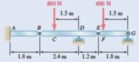
Fig. P10.53 and P10.54
Find the force representing the reaction at A using the virtual work method.
Find the couple representing the reaction at A using the virtual work method.
Answer to Problem 10.53P
The force representing the reaction at A is
The couple representing the reaction at A is
Explanation of Solution
Find the force at A;
Show the free-body diagram of the continuous beam as in Figure 1.
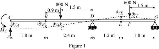
Consider the member AB is horizontal.
The vertical displacement at point A is
Find the vertical displacement
Find the vertical displacement
Find the vertical displacement
Find the vertical displacement
Use the concept of virtual work;
Substitute
Therefore, the force representing the reaction at A is
Find the couple at A;
Show the free-body diagram of the continuous beam as in Figure 2.
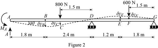
Rotate the member AB in the beam through
Find the vertical reaction
Find the vertical displacement
Find the vertical displacement
Find the vertical displacement
Use the concept of virtual work;
Substitute
Therefore, the couple representing the reaction at A is
Want to see more full solutions like this?
Chapter 10 Solutions
Vector Mechanics for Engineers: Statics


- (a) Determine the maximum allowable horizontal span for a uniform cable with a weight per unit length of w if the tension in the cable is not to exceed a given value Tm. (b) Using the result of part a , determine the maximum span of a steel wire for which w = 0.25 lb/ft and Tm = 8000 lb.arrow_forwardA spring of constant 15 kN/m connects points C and F of the linkage shown. Neglecting the weight of the spring and linkage, determine the force in the spring and the vertical motion of point G when a vertical downward 120-N force is applied (a) at point C ,( b) at points E and F.Fig. P10.8arrow_forwardA cable is placed around three parallel pipes. Knowing that the coefficients of friction are μs= 0.25 and μk= 0.20, determine (a) the smallest weight W for which equilibrium is maintained, (b) the largest weight W that can be raised if pipe B is slowly rotated counterclockwise while pipes A and C remain fixed.arrow_forward
- Collar A is connected as shown to a 50-lb load and can slide on a frictionless horizontal rod. Determine the magnitude of the force P required to maintain the equilibrium of the collar when (a) x = 4.5 in., (b) x 15 in.arrow_forwardKnowing that the coefficient of static friction is 0.30 between the rope and the horizontal pipe and that the smallest value of P for which equilibrium is maintained is 80 N, determine (a) the largest value of P for which equilibrium is maintained, (b) the coefficient of static friction between the rope and the vertical pipe.arrow_forwardThe pin at C is attached to member BCD and can slide along a slot cut in the fixed plate shown. Neglecting the effect of friction, derive an expression for the magnitude of the couple M required to maintain equilibrium when the force P that acts at D is directed (a) as shown, (b) vertically downward, (c) horizontally to the right.Fig. P10.18arrow_forward
- Two slender rods of negligible weight are pin-connected at C and attached to blocks A and B , each with a weight W . Knowing that P = 1.260 W and that the coefficient of static friction between the blocks and the horizontal surface is 0.30, determine the range of values of 0 between 0 and 180° for which equilibrium is maintained.arrow_forwardA cable is placed around three parallel pipes. Two of the pipes are fixed and do not rotate; the third pipe is slowly rotated. Knowing that the coefficients of friction are μs= 0.25 and μk= 0.20, determine the largest weight W that can be raised (a) if only pipe A is rotated counterclockwise, (b) if only pipe C is rotated clockwise.arrow_forwardCollars A and B are connected by a 25-in.-long wire and can slide freely on frictionless rods. Determine the distances x and z for which the equilibrium of the system is maintained when P=120 lb and Q=60 lb.arrow_forward
- Problem # 8: The five forces acting at the end of the boom satisfy the condition of equilibrium. Determine the values of T_{1} and T_{2} .arrow_forwardThe frictional resistance of a thrust bearing decreases as the shaft and bearing surfaces wear out. It is generally assumed that the wear is directly proportional to the distance traveled by any given point of the shaft and thus to the distance r from the point to the axis of the shaft. Assuming then that the normal force per unit area is inversely proportional to r , show that the magnitude M of the couple required to overcome the frictional resistance of a worn-out end bearing (with contact over the full circular area) is equal to 75 percent of the value given by Eq. (8.9) for a new bearing.arrow_forwardA wedge A of negligible weight is to be driven between two 100-lb blocks B and C resting on a horizontal surface. Knowing that the coefficient of static friction between all surfaces of contact is 0.35, determine the smallest force P required to start moving the wedge (a) if the blocks are equally free to move, (b) if block C is securely bolted to the horizontal surface.arrow_forward
 Elements Of ElectromagneticsMechanical EngineeringISBN:9780190698614Author:Sadiku, Matthew N. O.Publisher:Oxford University Press
 Mechanics of Materials (10th Edition)Mechanical EngineeringISBN:9780134319650Author:Russell C. HibbelerPublisher:PEARSON
 Thermodynamics: An Engineering ApproachMechanical EngineeringISBN:9781259822674Author:Yunus A. Cengel Dr., Michael A. BolesPublisher:McGraw-Hill Education
 Control Systems EngineeringMechanical EngineeringISBN:9781118170519Author:Norman S. NisePublisher:WILEY
 Mechanics of Materials (MindTap Course List)Mechanical EngineeringISBN:9781337093347Author:Barry J. Goodno, James M. GerePublisher:Cengage Learning
 Engineering Mechanics: StaticsMechanical EngineeringISBN:9781118807330Author:James L. Meriam, L. G. Kraige, J. N. BoltonPublisher:WILEY