Thermodynamics: An Engineering Approach
9th Edition
ISBN: 9781259822674
Author: Yunus A. Cengel Dr., Michael A. Boles
Publisher: McGraw-Hill Education
bartleby

Videos

Question
Book Icon
Chapter 10.9, Problem 109RP

(a)

To determine

The mass flow rate of air in the gas-turbine cycle.

(a)

Expert Solution
Check Mark

Answer to Problem 109RP

The mass flow rate of air in the gas-turbine cycle is 220.1kg/s.

Explanation of Solution

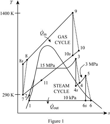
Show the T-s diagram as in Figure (1).

Thermodynamics: An Engineering Approach, Chapter 10.9, Problem 109RP

Express Prandtl number at state 8s.

Pr8s=P8sP7Pr7 (I)

Here, pressure at state 8s is P8s, pressure at state 7 is P7 and Prandtl number at state 7 is Pr7.

Express enthalpy at state 8.

h8=h7+h8sh7ηC (II)

Here, enthalpy at state 7 is h7, enthalpy at state 8s is h8s and the compressor efficiency is ηC.

Express Prandtl number at state 10s.

Pr10s=P10sP9Pr9 (III)

Here, pressure at state 10s is P10s, pressure at state 9 is P9 and Prandtl number at state 9 is Pr9.

Express enthalpy at state 10.

h10=h9ηT(h9h10s) (IV)

Here, enthalpy at state 9 is h9, compressor of the gas and steam turbine is ηT and enthalpy at state 10s is h10s.

Express enthalpy at state 1.

h1=hf@10kPa (V)

Here, enthalpy of saturation liquid at pressure of 10kPa is hf@10kPa.

Express specific volume at state 1.

v1=vf@10kPa (VI)

Here, specific volume of saturation liquid at pressure of 10kPa is vf@10kPa.

Express initial work input.

wpI,in=v1(P2P1) (VII)

Here, pressure at state 2 and 1 is P2andP1 respectively.

Express enthalpy at state 2.

h2=h1+wpI,in (VIII)

Express quality at state 4s.

x4s=s4ssf@3MPasfg@3MPa (IX)

Here, entropy at state 4s is s4s, entropy at saturation liquid and evaporation at pressure of 3MPa is sf@3MPaandsfg@3MPa respectively.

Express enthalpy at state 4s.

h4s=hf@3MPa+x4shfg@3MPa (X)

Here, enthalpy at saturation liquid and evaporation at pressure of 3MPa is hf@3MPaandhfg@3MPa respectively.

Express enthalpy at state 4.

h4=h3ηT(h3h4s) (XI)

Here, enthalpy at state 3 is h3 and enthalpy at state 4s is h4s.

Express quality at state 6s.

x6s=s6ssf@10kPasfg@10kPa (XII)

Here, entropy at state 6s is s6s, entropy at saturation liquid and evaporation at pressure of 10kPa is sf@10kPaandsfg@10kPa respectively.

Express enthalpy at state 6s.

h6s=hf@10MPa+x6shfg@10MPa (XIII)

Here, enthalpy at saturation liquid and evaporation at pressure of 10MPa is hf@10MPaandhfg@10MPa respectively.

Express enthalpy at state 6.

h6=h5ηT(h5h6s) (XIV)

Here, enthalpy at state 5 is h5 and enthalpy at state 6s is h6s.

Express the mass flow rate of air in the gas-turbine cycle from energy balance equation.

m˙air=h3h2h10h11m˙s (XV)

Here, enthalpy at state 10 is h10, enthalpy at state 11 is h11, enthalpy at state 3 and 2 is h3andh2 respectively, and mass flow rate of steam is m˙s.

Conclusion:

Refer Table A-17, “ideal gas properties of air”, and write the enthalpy at state 7 and Prandtl number at state 7 corresponding to temperature at state 7 of 290K.

h7=290.16kJ/kgPr7=1.2311

Substitute 8 for P8sP7 and 1.2311 for Pr7 in Equation (I).

Pr8s=8(1.2311)=9.849

Refer Table A-17, “ideal gas properties of air”, and write the enthalpy at state 8s corresponding to Prandtl number at state 8s of 9.849 using an interpolation method.

Write the formula of interpolation method of two variables.

y2=(x2x1)(y3y1)(x3x1)+y1 (XVI)

Here, the variables denote by x and y is Prandtl number at state8s and enthalpy at state 8s respectively.

Show the enthalpy at state 8s corresponding to Prandtl number as in Table (1).

Prandtl number at state 8s

Pr8s

Enthalpy at state 8s

h8s(kJ/kg)

9.684 (x1)523.63 (y1)
9.849 (x2)(y2=?)
10.37 (x3)533.98 (y3)

Substitute 9.684,9.849and10.37 for x1,x2andx3 respectively, 523.63kJ/kg for y1 and 533.98kJ/kg for y3 in Equation (XVI).

y2=(9.8499.684)(533.98kJ/kg523.63kJ/kg)(10.379.684)+523.63kJ/kg=526.12kJ/kg=h8s

Thus, enthalpy at state 8s corresponding to Prandtl number at state 8s of 9.849 is,

h8s=526.12kJ/kg

Substitute 290.16kJ/kg for h7, 526.12kJ/kg for h8s and 0.85 for ηC in Equation (II).

h8=290.16kJ/kg+[526.12kJ/kg290.16kJ/kg0.85]=567.76kJ/kg

Refer Table A-17, “ideal gas properties of air”, and write the enthalpy at state 9 and Prandtl number at state 9 corresponding to temperature at state 9 of 1400K.

h9=1515.42kJ/kgPr9=450.5

Here, enthalpy at state 9 is h9 and Prandtl number at state 9 is Pr9.

Substitute 18 for P10sP9 and 450.5 for Pr9 in Equation (III).

Pr10s=18(450.5)=56.3

Refer Table A-17, “ideal gas properties of air”, and write the enthalpy at state 10s corresponding to Prandtl number at state 10s of 56.3 using an interpolation method.

Show the enthalpy at state 10s corresponding to Prandtl number as in Table (2).

Prandtl number at state 10s

Pr10s

Enthalpy at state 10s

h10s(kJ/kg)

52.59 (x1)843.98 (y1)
56.3 (x2)(y2=?)
57.60 (x3)866.08 (y3)

Use excels and substitutes the values from Table (II) in Equation (XVI) to get,

h10s=860.35kJ/kg

Here, enthalpy at state 10s is h10s.

Substitute 1515.42kJ/kg for h9, 0.90 for ηT and 860.35kJ/kg for h10s in Equation (IV).

h10=1515.42kJ/kg(0.90)(1515.42kJ/kg860.35kJ/kg)=925.86kJ/kg

Refer Table A-17, “ideal gas properties of air”, and write the enthalpy at state 11 corresponding to temperature at state 11 of 520K.

h11=523.63kJ/kg

Here, enthalpy at state 11 is h11.

Refer Table A-5, “saturated water-pressure table”, and write the properties at pressure of 10kPa.

hf@10kPa=191.81kJ/kgvf@10kPa=0.00101m3/kg

Substitute 191.81kJ/kg for hf@10kPa in Equation (V).

h1=191.81kJ/kg

Substitute 0.00101m3/kg for vf@10kPa in Equation (VI).

v1=0.00101m3/kg

Substitute 0.00101m3/kg for v1, 15MPa for P2 and 10kPa for P1 in Equation (VII).

wpI,in=(0.00101m3/kg)(15MPa10kPa)=(0.00101m3/kg)(15,000kPa10kPa)kJkPam3=15.14kJ/kg

Substitute 191.81kJ/kg for h1 and 15.14kJ/kg for wpI,in in Equation (VIII).

h2=191.81kJ/kg+15.14kJ/kg=206.95kJ/kg

Refer Table A-6, “superheated water”, and write the properties corresponding to pressure at state 3 of 15MPa and temperature at state 3 of 450°C.

h3=3157.9kJ/kgs3=6.1428kJ/kgK

Here, enthalpy and entropy at state 3 is h3ands3 respectively.

Due to throttling process, entropy at state 3 is equal to entropy at state 4s.

s3=s4s=6.1428kJ/kgK

Refer Table A-5, “saturated water-pressure table”, and write the properties corresponding to pressure of 3MPa(3000kPa).

sf@3MPa=2.6454kJ/kgKsfg@3MPa=3.5402kJ/kgKhf@3MPa=1008.3kJ/kghfg@3MPa=1794.9kJ/kg

Substitute 6.1428kJ/kgK for s4s, 2.6454kJ/kgK for sf@3MPa and 3.5402kJ/kgK for sfg@3MPa in Equation (IX).

x4s=6.1428kJ/kgK2.6454kJ/kgK3.5402kJ/kgK=0.9880

Substitute 0.9880 for x4s, 1008.3kJ/kg for hf@3MPa and 1794.9kJ/kg for hfg@3MPa in Equation (X).

h4s=1008.3kJ/kg+(0.9880)(1794.9kJ/kg)=2781.7kJ/kg

Substitute 3157.9kJ/kg for h3, 0.90 for ηT and 2781.7kJ/kg for h4s in Equation (XI).

h4=3157.9kJ/kg(0.90)(3157.9kJ/kg2781.7kJ/kg)=2819.4kJ/kg

Refer Table A-6, “superheated water”, and write the properties corresponding to pressure at state 5 of 3MPa and temperature at state 5 of 500°C.

h5=3457.2kJ/kgs5=7.2359kJ/kgK

Here, enthalpy and entropy at state 5 is h5ands5 respectively.

Due to throttling process, entropy at state 5 is equal to entropy at state 6s.

s5=s6s=7.2359kJ/kgK

Refer Table A-5, “saturated water-pressure table”, and write the properties corresponding to pressure of 10kPa.

sf@10kPa=0.6492kJ/kgKsfg@10kPa=7.4996kJ/kgKhf@10kPa=191.81kJ/kghfg@10kPa=2392.1kJ/kg

Substitute 7.2359kJ/kgK for s6s, 0.6492kJ/kgK for sf@10kPa and 7.4996kJ/kgK for sfg@10kPa in Equation (XII).

x6s=7.2359kJ/kgK0.6492kJ/kgK7.4996kJ/kgK=0.8783

Substitute 0.8783 for x6s, 191.81kJ/kg for hf@10kPa and 2392.1kJ/kg for hfg@10kPa in Equation (XIII).

h6s=191.81kJ/kg+(0.8783)(2392.1kJ/kg)=2292.7kJ/kg

Substitute 3457.2kJ/kg for h5, 0.90 for ηT and 2292.7kJ/kg for h6s in Equation (XIV).

h6=3457.2kJ/kg(0.90)(3457.2kJ/kg2292.7kJ/kg)=2409.1kJ/kg

Substitute 3157.9kJ/kg for h3, 206.95kJ/kg for h2, 925.862kJ/kg for h10, 523.63kJ/kg for h11, and 30kg/s for m˙s in Equation (V).

m˙air=3157.9kJ/kg206.95kJ/kg925.862kJ/kg523.63kJ/kg(30kg/s)=220.1kg/s

Hence, the mass flow rate of air in the gas-turbine cycle is 220.1kg/s.

(b)

To determine

The rate of total heat input.

(b)

Expert Solution
Check Mark

Answer to Problem 109RP

The rate of total heat input is 227,700kW.

Explanation of Solution

Express the rate of total heat input.

Q˙in=m˙air(h9h8)+m˙s(h5h4) (XVII)

Conclusion:

Substitute 220.1kg/s for m˙air, 30kg/s for m˙s, 1515.42kJ/kg for h9, 567.76kJ/kg for h8, 3457.2kJ/kg for h5 and 2819.4kJ/kg for h4 in Equation (XVII).

Q˙in={(220.1kg/s)[(1515.42567.76)kJ/kg]+(30kg/s)[(3457.22819.4)kJ/kg]}=227,700kJ/s[kWkJ/s]=227,700kW

Hence, the rate of total heat input is 227,700kW.

(c)

To determine

The thermal efficiency of the combined cycle.

(c)

Expert Solution
Check Mark

Answer to Problem 109RP

The thermal efficiency of the combined cycle is 48.2%.

Explanation of Solution

Express the rate of total heat output.

Q˙out=m˙air(h11h7)+m˙s(h6h1) (XVIII)

Express the thermal efficiency of the combined cycle.

ηth=1Q˙outQ˙in (XIX)

Conclusion:

Substitute 220.1kg/s for m˙air, 30kg/s for m˙s, 523.63kJ/kg for h11, 290.16kJ/kg for h7, 2409.1kJ/kg for h6 and 191.81kJ/kg for h1 in Equation (XVIII).

Q˙out={(220.1kg/s)[(523.63290.16)kJ/kg]+(30kg/s)[(2409.1191.81)kJ/kg]}=117,900kJ/s[kWkJ/s]=117,900kW

Substitute 117,900kW for Q˙out and 227,700kW for Q˙in in Equation (XIX).

ηth=1117,900kW227,700kW=0.482=48.2%

Hence, the thermal efficiency of the combined cycle is 48.2%.

Want to see more full solutions like this?

Subscribe now to access step-by-step solutions to millions of textbook problems written by subject matter experts!
Students have asked these similar questions
Show that the air standard efficiency of a gas turbine can be expressed in terms ofpressure ratio only.
A plant engineer suggests ending this practice. She proposes to run cooling water through the outer surface of the casing to cool the steam as it flows through the turbine. This way, she reasons, the entropy of the steam will decrease, the performance of the turbine will improve, and as a result the work output of the turbine will increase. How would you evaluate this proposal?
Air at 200 kPa and 950 K enters an adiabatic nozzle at low velocity and is discharged at a pressure of 110 kPa. If the isentropic efficiency of the nozzle is 92 percent, determine the maximum possible exit velocity.

Chapter 10 Solutions

Thermodynamics: An Engineering Approach

Ch. 10.9 - How do actual vapor power cycles differ from...Ch. 10.9 - Compare the pressures at the inlet and the exit of...Ch. 10.9 - The entropy of steam increases in actual steam...Ch. 10.9 - Is it possible to maintain a pressure of 10 kPa in...Ch. 10.9 - A simple ideal Rankine cycle with water as the...Ch. 10.9 - A simple ideal Rankine cycle with water as the...Ch. 10.9 - A simple ideal Rankine cycle which uses water as...Ch. 10.9 - Consider a solar-pond power plant that operates on...Ch. 10.9 - Consider a 210-MW steam power plant that operates...Ch. 10.9 - Consider a 210-MW steam power plant that operates...Ch. 10.9 - A simple ideal Rankine cycle with water as the...Ch. 10.9 - A simple ideal Rankine cycle with water as the...Ch. 10.9 - A steam Rankine cycle operates between the...Ch. 10.9 - A steam Rankine cycle operates between the...Ch. 10.9 - A simple Rankine cycle uses water as the working...Ch. 10.9 - The net work output and the thermal efficiency for...Ch. 10.9 - A binary geothermal power plant uses geothermal...Ch. 10.9 - Consider a coal-fired steam power plant that...Ch. 10.9 - Show the ideal Rankine cycle with three stages of...Ch. 10.9 - Is there an optimal pressure for reheating the...Ch. 10.9 - How do the following quantities change when a...Ch. 10.9 - Consider a simple ideal Rankine cycle and an ideal...Ch. 10.9 - Consider a steam power plant that operates on the...Ch. 10.9 - Consider a steam power plant that operates on the...Ch. 10.9 - An ideal reheat Rankine cycle with water as the...Ch. 10.9 - Steam enters the high-pressure turbine of a steam...Ch. 10.9 - An ideal reheat Rankine cycle with water as the...Ch. 10.9 - A steam power plant operates on an ideal reheat...Ch. 10.9 - Consider a steam power plant that operates on a...Ch. 10.9 - Repeat Prob. 1041 assuming both the pump and the...Ch. 10.9 - Prob. 43PCh. 10.9 - Prob. 44PCh. 10.9 - How do open feedwater heaters differ from closed...Ch. 10.9 - How do the following quantities change when the...Ch. 10.9 - Cold feedwater enters a 200-kPa open feedwater...Ch. 10.9 - In a regenerative Rankine cycle. the closed...Ch. 10.9 - A steam power plant operates on an ideal...Ch. 10.9 - A steam power plant operates on an ideal...Ch. 10.9 - A steam power plant operates on an ideal...Ch. 10.9 - Consider an ideal steam regenerative Rankine cycle...Ch. 10.9 - Consider a steam power plant that operates on the...Ch. 10.9 - Consider a steam power plant that operates on the...Ch. 10.9 - Consider a steam power plant that operates on the...Ch. 10.9 - A steam power plant operates on an ideal...Ch. 10.9 - Repeat Prob. 1060, but replace the open feedwater...Ch. 10.9 - A steam power plant operates on an ideal...Ch. 10.9 - A simple ideal Rankine cycle with water as the...Ch. 10.9 - Prob. 64PCh. 10.9 - An ideal reheat Rankine cycle with water as the...Ch. 10.9 - Consider a steam power plant that operates on a...Ch. 10.9 - Prob. 67PCh. 10.9 - A steam power plant operates on an ideal...Ch. 10.9 - The schematic of a single-flash geothermal power...Ch. 10.9 - What is the difference between cogeneration and...Ch. 10.9 - Prob. 71PCh. 10.9 - Prob. 72PCh. 10.9 - Consider a cogeneration plant for which the...Ch. 10.9 - Steam is generated in the boiler of a cogeneration...Ch. 10.9 - A large food-processing plant requires 1.5 lbm/s...Ch. 10.9 - An ideal cogeneration steam plant is to generate...Ch. 10.9 - Steam is generated in the boiler of a cogeneration...Ch. 10.9 - Consider a cogeneration power plant modified with...Ch. 10.9 - Prob. 80PCh. 10.9 - Why is the combined gassteam cycle more efficient...Ch. 10.9 - The gas-turbine portion of a combined gassteam...Ch. 10.9 - A combined gassteam power cycle uses a simple gas...Ch. 10.9 - Reconsider Prob. 1083. An ideal regenerator is...Ch. 10.9 - Reconsider Prob. 1083. Determine which components...Ch. 10.9 - Consider a combined gassteam power plant that has...Ch. 10.9 - Prob. 89PCh. 10.9 - What is the difference between the binary vapor...Ch. 10.9 - Why is mercury a suitable working fluid for the...Ch. 10.9 - Why is steam not an ideal working fluid for vapor...Ch. 10.9 - By writing an energy balance on the heat exchanger...Ch. 10.9 - Prob. 94RPCh. 10.9 - Steam enters the turbine of a steam power plant...Ch. 10.9 - Consider a steam power plant operating on the...Ch. 10.9 - A steam power plant operates on an ideal Rankine...Ch. 10.9 - Consider a steam power plant that operates on a...Ch. 10.9 - Repeat Prob. 1098 assuming both the pump and the...Ch. 10.9 - Consider an ideal reheatregenerative Rankine cycle...Ch. 10.9 - Prob. 101RPCh. 10.9 - A textile plant requires 4 kg/s of saturated steam...Ch. 10.9 - Consider a cogeneration power plant that is...Ch. 10.9 - Prob. 104RPCh. 10.9 - Prob. 105RPCh. 10.9 - Reconsider Prob. 10105E. It has been suggested...Ch. 10.9 - Reconsider Prob. 10106E. During winter, the system...Ch. 10.9 - Prob. 108RPCh. 10.9 - Prob. 109RPCh. 10.9 - A steam power plant operates on an ideal...Ch. 10.9 - A Rankine steam cycle modified for reheat, a...Ch. 10.9 - Show that the thermal efficiency of a combined...Ch. 10.9 - Prob. 118RPCh. 10.9 - A solar collector system delivers heat to a power...Ch. 10.9 - Starting with Eq. 1020, show that the exergy...Ch. 10.9 - Consider a simple ideal Rankine cycle with fixed...Ch. 10.9 - Consider a simple ideal Rankine cycle. If the...Ch. 10.9 - Consider a simple ideal Rankine cycle with fixed...Ch. 10.9 - Consider a simple ideal Rankine cycle with fixed...Ch. 10.9 - Consider a steady-flow Carnot cycle with water as...Ch. 10.9 - Prob. 126FEPCh. 10.9 - Prob. 127FEPCh. 10.9 - A simple ideal Rankine cycle operates between the...Ch. 10.9 - Pressurized feedwater in a steam power plant is to...Ch. 10.9 - Consider a steam power plant that operates on the...Ch. 10.9 - Consider a combined gas-steam power plant. Water...
Knowledge Booster
Background pattern image
Mechanical Engineering
Learn more about
Need a deep-dive on the concept behind this application? Look no further. Learn more about this topic, mechanical-engineering and related others by exploring similar questions and additional content below.
Similar questions
SEE MORE QUESTIONS
Recommended textbooks for you
Text book image
Elements Of Electromagnetics
Mechanical Engineering
ISBN:9780190698614
Author:Sadiku, Matthew N. O.
Publisher:Oxford University Press
Text book image
Mechanics of Materials (10th Edition)
Mechanical Engineering
ISBN:9780134319650
Author:Russell C. Hibbeler
Publisher:PEARSON
Text book image
Thermodynamics: An Engineering Approach
Mechanical Engineering
ISBN:9781259822674
Author:Yunus A. Cengel Dr., Michael A. Boles
Publisher:McGraw-Hill Education
Text book image
Control Systems Engineering
Mechanical Engineering
ISBN:9781118170519
Author:Norman S. Nise
Publisher:WILEY
Text book image
Mechanics of Materials (MindTap Course List)
Mechanical Engineering
ISBN:9781337093347
Author:Barry J. Goodno, James M. Gere
Publisher:Cengage Learning
Text book image
Engineering Mechanics: Statics
Mechanical Engineering
ISBN:9781118807330
Author:James L. Meriam, L. G. Kraige, J. N. Bolton
Publisher:WILEY
Power Plant Explained | Working Principles; Author: RealPars;https://www.youtube.com/watch?v=HGVDu1z5YQ8;License: Standard YouTube License, CC-BY