
Videos
A steam power plant operates on an ideal reheat–regenerative Rankine cycle with one reheater and two open feedwater heaters. Steam enters the high-pressure turbine at 1500 psia and 1100°F and leaves the low- pressure turbine at 1 psia. Steam is extracted from the turbine at 250 and 40 psia, and it is reheated to 1000°F at a pressure of 140 psia. Water leaves both feedwater heaters as a saturated liquid. Heat is transferred to the steam in the boiler at a rate of 4 × 10⁵ Btu/s. Show the cycle on a T-s diagram with respect to saturation lines, and determine (a) the mass flow rate of steam through the boiler, (b) the net power output of the plant, and (c) the thermal efficiency of the cycle.
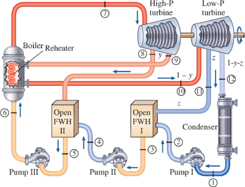
FIGURE P10–62E
(a)
The mass flow rate of steam flowing through the boiler.
Answer to Problem 62P
The mass flow rate of steam flowing through the boiler is
Explanation of Solution
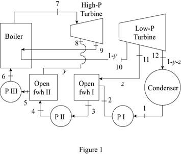
Draw the schematic layout of the given power plant that operates on an ideal reheat-regenerative Rankine cycle as shown in Figure 1.
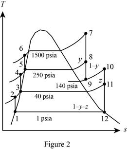
Draw the
Figure 2.
Here, water (steam) is the working fluid of the ideal regenerative Rankine cycle. The cycle involves three pumps.
Write the formula for work done by the pump during process 1-2.
Here, the specific volume is
Write the formula for enthalpy
Write the formula for work done by the pump during process 3-4.
Here, the specific volume is
Write the formula for enthalpy
Write the formula for work done by the pump during process 5-6.
Here, the specific volume is
Write the formula for enthalpy
Before reheating.
At state 9:
The steam expanded to the pressure of
After reheating.
At state 10:
The steam is reheated to the temperature of
At state 12:
The steam enters the condenser at the pressure of
The quality of water at state 12 is expressed as follows.
The enthalpy at state 12 is expressed as follows.
Here, the enthalpy is
Write the formula for heat in
Here, the mass fraction steam extracted from the turbine to the feed water entering the boiler via feed water heater-II
Write the general equation of energy balance equation.
Here, the rate of net energy inlet is
At steady state the rate of change of net energy of the system
Refer Equation (XI).
Write the energy balance equation for open feed water heater-II.
Rewrite the Equation (XII) in terms of mass fraction
Refer Equation (XI).
Write the energy balance equation for open feed water heater-I.
Rewrite the Equation (XIV) in terms of mass fraction
Write the formula for mass flow rate.
Here, the rate of heat input is
At state 1:
The water exits the condenser as a saturated liquid at the pressure of
Refer Table A-5E, “Saturated water-Pressure table”.
The enthalpy
At state 3: (Pump II inlet)
The water exits the open feed water heater-I as a saturated liquid at the pressure of
Refer Table A-5E, “Saturated water-Pressure table”.
The enthalpy
At state 5: (Pump III inlet)
The water exits the open feed water heater-II as a saturated liquid at the pressure of
Refer Table A-5E, “Saturated water-Pressure table”.
The enthalpy
At state 7: (H.P. Turbine inlet)
The steam enters the turbine as superheated vapor.
Refer Table A-6E, “Superheated water”.
The enthalpy
Refer Figure 2.
At state 8:
The steam is extracted at the pressure of
Refer Table A-6E, “Superheated water”.
The enthalpy
At state 9:
The steam is expanded at the pressure of
Refer Table A-6E, “Superheated water”.
The enthalpy
At state 10:
The steam is reheated to the temperature of
Refer Table A-6E, “Superheated water”.
The enthalpy
Refer Figure 2.
At state 11:
The steam is expanded at the pressure of
Refer Table A-6E, “Superheated water”.
The enthalpy
At state 12: (Condenser inlet)
The steam enters the condenser at the pressure of
Refer Table A-5E, “Saturated water-Pressure table”.
Obtain the following properties corresponding to the pressure of
Conclusion:
Substitute
Substitute
Substitute
Equation (III).
Substitute
Substitute
Equation (V).
Substitute
From Figure 2.
Substitute
Substitute
Equation (VIII).
Consider the open feed water heater-II alone.
Substitute
Equation (XIII).
Consider the open feed water heater-I alone.
Substitute
Substitute
Substitute
Substitute
Thus, the mass flow rate of steam flowing through the boiler is
(b)
The net power output of the plant.
Answer to Problem 62P
The net power output of the plant is
Explanation of Solution
Write the formula for net power output of the cycle per unit mass.
Write the formula for net power output of the cycle.
Here, the mass flow rate is
Conclusion:
Substitute
Substitute
Thus, the net power output of the plant is
(c)
The thermal efficiency of the cycle.
Answer to Problem 62P
The thermal efficiency of the cycle is
Explanation of Solution
Write the formula for thermal efficiency of the cycle
Conclusion:
Substitute
Thus, the thermal efficiency of the cycle is
Want to see more full solutions like this?
Chapter 10 Solutions
Thermodynamics: An Engineering Approach
Additional Engineering Textbook Solutions
Vector Mechanics for Engineers: Statics and Dynamics
Fox and McDonald's Introduction to Fluid Mechanics
Applied Statics and Strength of Materials (6th Edition)
Heat and Mass Transfer: Fundamentals and Applications
Fundamentals of Aerodynamics
Engineering Mechanics: Statics & Dynamics (14th Edition)


- A Combined power plant consists of a gas turbine unit and a steam turbine unit. The exhaust gas from the open-cycle gas turbine is the supply gas to the steam generator of the steam turbine cycle at which additional fuel is burned in the gas. The pressure ratio for the gas turbine is 16, the air inlet temperature is 180C, and the maximum cycle temperature is 8000C. Combustion in the steam generator raises the gas temperature to 8000C and the gas leaves the generator to the chimney at 1100C. Steam is supplied to the steam turbine at 60 bar, 6500C, and the condenser pressure is 0.1 bar. The isentropic efficiencies of the air compressor, gas turbine, and steam turbine are 85%, 88%, and 87% respectively. Taking Cp = 1.11 Kj/kgK and adiabatic index= 1.33 for the combustion gases, and neglecting the effect of the mass flow rate of fuel, feed-pump work, and all pressure losses, calculate; The required flow rates of air and steam for a total output of 200 MW; The power output of each unit;…arrow_forwardHow does the thermal efficiency of an ideal Otto cycle change with the compression ratio of the engine and the specific heat ratio of the working fluid?arrow_forwardThermodynamics 2 Consider a steam power plant that operates on a reheat Rankine cycle and has a net power output of 91 MW. Steam enters the high-pressure turbine at 10 MPa and 500 C and the low-pressure turbine at 1 MPa and 500 C. Steam leaves the condenser as a saturated liquid at a pressure of 10 kPa. The isentropic efficiency of the turbine is 95 percent, and that of the pump is 90 percent. The required power input in the pump in MW.arrow_forward
- A Combined power plant consists of a gas turbine unit and a steam turbine unit. The exhaust gas from the open-cycle gas turbine is the supply gas to the steam generator of the steam turbine cycle at which additional fuel is burned in the gas. The pressure ratio for the gas turbine is 30 the air inlet temperature is 180C, and the maximum cycle temperature is 8000C. Combustion in the steam generator raises the gas temperature to 8000C and the gas leaves the generator to the chimney at 1100C. Steam is supplied to the steam turbine at 60 bar, 6500C, and the condenser pressure is 0.1 bar.The isentropic efficiencies of the air compressor, gas turbine, and steam turbine are 85%, 88%, and 87% respectively. Taking Cp = 1.11 Kj/kgK and adiabatic index= 1.33 for the combustion gases, and neglecting the effect of the mass flow rate of fuel, feed-pump work, and all pressure losses, calculate;a) The required flow rates of air and steam for a total output of 200 MW;b) The power output of each unit;c)…arrow_forwardConsider a steam power plant that operates on the ideal reheat Rankine cycle. The plant maintains the boiler at 5400 kPa, the reheat section 1100 kPa, and the condenser at 10 kPa. The mixture quality at the exit of both turbines is 94 %. Determine the following values. (1) The specific enthalpy at the exit of the high-pressure turbine. (2) The specific entropy at the exit of the high-pressure turbine. (3) The temperature at the inlet of the high-pressure turbine. (4) The temperature at the inlet of the low-pressure turbine. (5) The thermal efficiency of the cycle.arrow_forwardA steam power plant operates on an ideal reheat Rankine cycle between the pressure limits of 14 MPa and 10 kPa. The mass flow rate of steam through the cycle is 10 kg/s. Steam enters both stages of the turbine at 500°C. If the moisture content of the steam at the exit of the low-pressure turbine is not to exceed 12 percent, determine (a) the pressure at which reheating takes place, (b) the total rate of heat input in the boiler, and (c) the thermal efficiency of the cycle. Also, show the cycle on a T-s diagram with respect to saturation lines.arrow_forward
- Water is the working fluid in a regenerative Rankine cycle with one closed feedwater heater and one open feedwater heater. Steam enters the turbine at 1400 lbf/in.2 and 1150°F and expands to 500 lbf/in.2, where some of the steam is extracted and diverted to the closed feedwater heater. Condensate exiting the closed feedwater heater as saturated liquid at 500 lbf/in.2 undergoes a throttling process to 120 lbf/in.2 as it passes through a trap into the open feedwater heater.The feedwater leaves the closed feedwater heater at 1400 lbf/in.2 and a temperature equal to the saturation temperature at 500 lbf/in.2 The remaining steam expands through the second-stage turbine to 120 lbf/in.2, where some of the steam is extracted and diverted to the open feedwater heater operating at 120 lbf/in.2 Saturated liquid exits the open feedwater heater at 120 lbf/in.2The remaining steam expands through the third-stage turbine to the condenser pressure of 5 lbf/in.2 The turbine stages and the pumps each…arrow_forwardIn a steam power plant that operates based on a Rankine cycle, the operating pressures of the steam generator and the condenser are 10,000 and 10 kPa, respectively. If the turbine inlet stream is saturated vapor and the condenser outlet flow is saturated liquid, determine the specific heat transfers in the steam generator and the condenser, the specific work involved in the turbine and the pump, and the thermal efficiency and the BWR of the cycle. Also, if the power plant produces 250 MW power, determine the mass flow rate of the cycle’s working fluid.arrow_forwardWater is the working fluid in an ideal regenerative Rankine cycle with one open feedwater heater. Steam enters the turbine at 1400 lbf/in.2 and 1000°F and expands to 120 lbf/in.2, where some of the steam is extracted and diverted to the open feedwater heater operating at 120 lbf/in.2 The remaining steam expands through the second-stage turbine to the condenser pressure of 6 lbf/in.2 Saturated liquid exits the open feedwater heater at 120 lbf/in.2 The net power output of the cycle is 1 x 10⁸ Btu/h.Determine for the cycle:(a) the mass flow rate of steam entering the first stage of the turbine, in lb/h.(b) the rate of heat transfer, in Btu/h, to the working fluid passing through the steam generator.(c) the percent thermal efficiency.arrow_forward
- 2. A steam power plant operates on the Rankine cycle in which the steam enters the turbine at 16 MPa and 600°C and the condensate leaves the condenser at 10 kPa. If the isentropic efficiency of the turbine is 87 percent and the isentropic efficiency of the pump is 85 percent, determine (a) the thermal efficiency of the cycle and (b) the net power output of the plant for a mass flow rate of 15 kg/s.arrow_forwardA gas-turbine power plant operates on the simple Brayton cycle between the pressure limits of 100 and 1200 kPa. The working fluid is air, which enters the compressor at 30°C at a rate of 150 m3/min and leaves the turbine at 500°C. Using constant specific heats for air and assuming a compressor isentropic efficiency of 82 percent and a turbine isentropic efficiency of 88 percent, determine (a) the net power output, (b) the work ratio, and (c) the thermal efficiency.arrow_forwardConsider an ideal gas-turbine cycle with two stages of compression and two stages of expansion. The pressure ratio across each stage of the compressor and turbine is 3. The air enters each stage of the compressor at 300 K and each stage of the turbine at 1200 K. Determine the back work ratio and the thermal efficiency of the cycle, assuming no regenerator is used.arrow_forward
 Elements Of ElectromagneticsMechanical EngineeringISBN:9780190698614Author:Sadiku, Matthew N. O.Publisher:Oxford University Press
 Mechanics of Materials (10th Edition)Mechanical EngineeringISBN:9780134319650Author:Russell C. HibbelerPublisher:PEARSON
 Thermodynamics: An Engineering ApproachMechanical EngineeringISBN:9781259822674Author:Yunus A. Cengel Dr., Michael A. BolesPublisher:McGraw-Hill Education
 Control Systems EngineeringMechanical EngineeringISBN:9781118170519Author:Norman S. NisePublisher:WILEY
 Mechanics of Materials (MindTap Course List)Mechanical EngineeringISBN:9781337093347Author:Barry J. Goodno, James M. GerePublisher:Cengage Learning
 Engineering Mechanics: StaticsMechanical EngineeringISBN:9781118807330Author:James L. Meriam, L. G. Kraige, J. N. BoltonPublisher:WILEY