
Videos
The schematic of a single-flash geothermal power plant with state numbers is given in Fig. P10–69. Geothermal resource exists as saturated liquid at 230°C. The geothermal liquid is withdrawn from the production well at a rate of 230 kg/s and is flashed to a pressure of 500 kPa by an essentially isenthalpic flashing process where the resulting vapor is separated from the liquid in a separator and is directed to the turbine. The steam leaves the turbine at 10 kPa with a moisture content of 5 percent and enters the condenser where it is condensed; it is routed to a reinjection well along with the liquid coming off the separator. Determine (a) the power output of the turbine and the thermal efficiency of the plant, (b) the exergy of the geothermal liquid at the exit of the flash chamber, and the exergy destructions and the second-law efficiencies for (c) the turbine and (d) the entire plant.
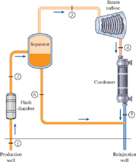
FIGURE P10–69
(a)
The temperature of the steam after the flashing process and the power output from the turbine if the pressure of the steam at the exit of flash chamber is
Answer to Problem 69P
The power output turbine is
The thermal efficiency of the plant is
Explanation of Solution
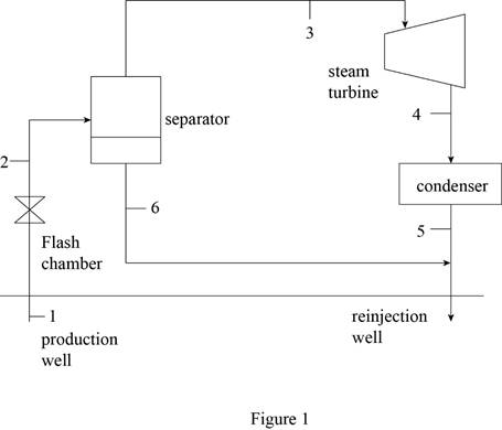
Draw schematic diagram of single flash geothermal power plant as shown in Figure 1.
Write the general energy rate balance equation.
Here, the rate of total energy in is
Consider the system operates at steady state. Hence, the rate of change in net energy of the system becomes zero.
The Equation (I) is reduced as follows.
Refer Figure 1.
The flash chamber is nothing but the expansion valve. At expansion valve, the enthalpy kept constant.
Express the energy balance equation for the flash chamber.
Express the energy balance equation for the separator.
Express the energy balance equation for the turbine.
At state 1:
The geothermal water is extracted at the state of saturated liquid at the temperature of
The enthalpy and entropy at state 1 is as follows.
Refer Table A-4, “Saturated water-Temperature table”
The enthalpy
Refer Table A-1, “Molar mass, gas constant, and critical-point properties”.
At state 2:
The exit pressure of the flash chamber is
The geothermal steam is flashed at constant enthalpy. The exit steam of the flash chamber is at the quality of
Here, the fluid enthalpy is
Refer Table A-5, “Saturated water-Pressure table”.
Obtain the following corresponding to the pressure of
The entropy
Write the formula for mass flow rate of vapor at entering the turbine.
Here, the mass flow rate is
At state 3:
There is no pressure drop in the separator. The separator separates vapor and liquid form the flashed steam, and the separated vapor alone sent to the turbine.
The enthalpy
Refer Table A-5, “Saturated water-Pressure table”.
The enthalpy
At state 4:
The steam is at the state of saturated mixture at the pressure of
The quality at state 4 is as follows.
The enthalpy
Refer Table A-5, “Saturated water-Pressure table”.
Obtain the following corresponding to the pressure of
At state 6:
The saturated water only exits at the bottom of the separator. The enthalpy
Refer Table A-5, “Saturated water-Pressure table”.
The enthalpy
Write the formula for net energy input of the plant.
Write the formula for thermal efficiency.
Consider, the surrounding temperature is
The surrounding enthalpy
Refer Table A-4, “Saturated water-Temperature table”.
The enthalpy
Conclusion:
Substitute
Substitute
Substitute
Substitute
Equation (VII).
Substitute
Substitute
Equation (III).
Thus, the power output turbine is
Substitute
Equation (IX).
Substitute
Thus, the thermal efficiency of the plant is
(b)
The exergy of the geothermal liquid at the exit of the flash chamber, and the exergy destructions.
Answer to Problem 69P
The exergy of the geothermal liquid at the exit of the flash chamber, and the exergy destruction is
Explanation of Solution
Write the formula for exergy of the steam at their respective process state.
Here, the enthalpy is
Write the formula for rate of exergy destruction at the exit of flash chamber (state 6).
Here, the rate of exergy destruction at state 6 is
Conclusion:
For process state 1:
Substitute
For process state 2:
Substitute
For process state 3:
Substitute
For process state 4:
Substitute
For process state 6:
Substitute
The mass flow rate of water at the bottom exit of separator (state 6) is expressed as follows.
Substitute
Thus, the exergy of the geothermal liquid at the exit of the flash chamber, and the exergy destruction is
(c)
The exergy destruction and second law of efficiency for the turbine.
Answer to Problem 69P
The exergy destruction and second law of efficiency for the turbine is
Explanation of Solution
Write the formula for rate of exergy destruction of the turbine.
Write the formula for second law of efficiency of the turbine.
Conclusion:
Substitute
Substitute
Thus, the exergy destruction and second law of efficiency for the turbine is
(d)
The exergy destruction and second law of efficiency for the entire plant.
Answer to Problem 69P
The exergy destruction and second law of efficiency for the plant is
Explanation of Solution
Write the formula for rate of exergy input of the plant.
Write the formula for rate of exergy destruction of the plant.
Write the formula for second law of efficiency of the plant.
Conclusion:
Substitute
Substitute
Substitute
Thus, the exergy destruction and second law of efficiency for the plant is
Want to see more full solutions like this?
Chapter 10 Solutions
Thermodynamics: An Engineering Approach


- CONSIDER A STEAM POWER PLANT OPERATING ON THE IDEAL REHEAT RANKINE CYCLE. STEAM ENTERS THE HIGH-PRESSURE TURBINE AT 15 MPA AND 600 °C AND IS CONDENSED IN THE CONDENSER AT A PRESSURE OF 10 KPA. ASSUMING THE REHEAT TEMPERATURE IS ALSO 600 °C AND IF THE MOISTURE CONTENT OF THE STEAM AT THE EXIT OF THE LOW-PRESSURE TURBINE IS NOT TO EXCEED 10%, DETERMINE: THE PRESSURE AT WHICH STEAM SHOULD BE REHEATED,arrow_forwardConsider a 210-MW steam power plant that operates on a simple ideal Rankine cycle. Steam enters the turbine at 10 MPa and 500C and is cooled in the condenser at a pressure of 10 kPa. Assuming an isentropic efficiency of 85 percent for both the turbine and the pump, determine the specific enthalpy (kJ/kg) at the condenser outlet. (Use 2 decimal places for the final answer.)arrow_forwardConsider a steam power plant operating on a simple Rankine cycle. Steam enters the turbine at 15 MPa and 650°C and is condensed in the condenser at a pressure of 15 kPa. Assuming an isentropic efficiency of 84% and 86% for the pump and turbine, respectively, determine the actual Qin (kJ/kg). (Use 2 decimal places for the final answer.)arrow_forward
- The schematic of a single-flash geothermal power plant with state numbers is given in Fig. P7-73. Geothermal resource exists as saturated liquid at 230°C. The geothermal liquid is withdrawn from the production well at a rate of 230 kg/s, and is flashed to a pressure of 500 kPa by an essentially isenthalpic flashing process where the resulting vapor is separated from the liquid in a separator and directed to the turbine. The steam leaves the turbine at 10 kPa with a moisture content of 10 percent and enters the condenser where it is condensed and routed to a reinjection well along with the liquid coming off the separator. Determine (a) the mass flow rate of steam through the turbine, (b) the isentropic efficiency of the turbine, (c) the power output of the turbine, and (d) the thermal efficiency of the plant (the ratio of the turbine work output to the energy of the geothermal fluid relative to standard ambient conditions).arrow_forwardConsider a steam power plant operating on a simple Rankine cycle. Steam enters the turbine at 15 MPa and 650°C and is condensed in the condenser at a pressure of 15 kPa. Assuming an isentropic efficiency of 84% and 86% for the pump and turbine, respectively, determine the actual Wnet (kJ/kg). (Use 2 decimal places for the final answer.)arrow_forwardConsider a 210-MW steam power plant that operates on a simple ideal Rankine cycle. Steam enters the turbine at 10 MPa and 500C and is cooled in the condenser at a pressure of 10 kPa. Assuming an isentropic efficiency of 85 percent for both the turbine and the pump, determine the specific enthalpy (kJ/kg) at the boiler outlet. (Use 2 decimal places for the final answer.)arrow_forward
- Consider a 210-MW steam power plant that operates on a simple ideal Rankine cycle. Steam enters the turbine at 10 MPa and 500C and is cooled in the condenser at a pressure of 10 kPa. Assuming an isentropic efficiency of 85 percent for both the turbine and the pump, determine the actual thermal efficiency (%) of the cycle. (Use 2 decimal places for the final answer.)arrow_forwardConsider a 210-MW steam power plant that operates on a simple ideal Rankine cycle. Steam enters the turbine at 10 MPa and 500C and is cooled in the condenser at a pressure of 10 kPa. Assuming an isentropic efficiency of 85 percent for both the turbine and the pump, determine: the quality of the steam at the turbine exit the thermal efficiency of the cycle specific enthalpy (kJ/kg) at the condenser both inlet and outlet specific enthalpy (kJ/kg) at the boiler both inlet and outlet WT, WP, WNet(kJ/kg) actual Qin (kJ/kg) and actual Qout (kJ/kg).arrow_forwardConsider a 210-MW steam power plant that operates on a simple ideal Rankine cycle. Steam enters the turbine at 10 MPa and 500C and is cooled in the condenser at a pressure of 10 kPa. Assuming an isentropic efficiency of 85 percent for both the turbine and the pump, determine the actual mass flow rate (kg/s) of the steam. (Use 2 decimal places for the final answer.)arrow_forward
- Consider a 210-MW steam power plant that operates on a simple ideal Rankine cycle. Steam enters the turbine at 10 MPa and 500C and is cooled in the condenser at a pressure of 10 kPa. Assuming an isentropic efficiency of 85 percent for both the turbine and the pump, determine the quality ofthe steam at the turbine exit, the thermal efficiency of the cycle, specific enthalpy (kJ/kg) at the condenser, and actual Qin (kJ/kg).arrow_forwardRefrigerant-134a enters the compressor of a refrigerator at 140 kPa and -10°C at a rate of 0.3 m3/min and leaves at 1 MPa. The isentropic efficiency of the compressor is 78 percent. The refrigerant enters the throttling valve at 0.95 MPa and 30°C and leaves the evaporator as saturated vapor at -18.5°C. Show the cycle on a T-s diagram with respect to saturation lines, and determine (a) the power input to the compressor, (b) the rate of heat removal from the refrigerated space, and (c) the pressure drop andrate of heat gain in the line between the evaporator and the compressor. answers 1.88 kW, 7.11 kW, 1.72 kPa, 0.24 kWarrow_forwardConsider a 210-MW steam power plant that operates on a simple ideal Rankine cycle. Steam enters the turbine at 10 MPa and 500C and is cooled in the condenser at a pressure of 10 kPa. Assuming an isentropic efficiency of 85 percent for both the turbine and the pump, determine the actual WT (kJ/kg). (Use 2 decimal places for the final answer.)arrow_forward
 Elements Of ElectromagneticsMechanical EngineeringISBN:9780190698614Author:Sadiku, Matthew N. O.Publisher:Oxford University Press
 Mechanics of Materials (10th Edition)Mechanical EngineeringISBN:9780134319650Author:Russell C. HibbelerPublisher:PEARSON
 Thermodynamics: An Engineering ApproachMechanical EngineeringISBN:9781259822674Author:Yunus A. Cengel Dr., Michael A. BolesPublisher:McGraw-Hill Education
 Control Systems EngineeringMechanical EngineeringISBN:9781118170519Author:Norman S. NisePublisher:WILEY
 Mechanics of Materials (MindTap Course List)Mechanical EngineeringISBN:9781337093347Author:Barry J. Goodno, James M. GerePublisher:Cengage Learning
 Engineering Mechanics: StaticsMechanical EngineeringISBN:9781118807330Author:James L. Meriam, L. G. Kraige, J. N. BoltonPublisher:WILEY