
Concept explainers
Videos
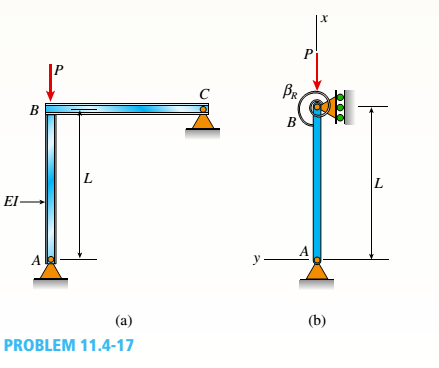
The frame ABC consists of two members AB and BC that are rigidly connected at joint B, as shown in part a of the figure. The frame has pin supports at A and C. A concentrated load P acts at joint B, thereby placing member AB in direct compression.
To assist in determining the buckling load for member AB, represent it as a pinned-end column, as shown in part b of the figure. At the top of the column, a rotational spring of stiffness ßRrepresents the restraining action of the horizontal beam BC on the column (note that the horizontal beam
provides resistance to rotation of joint B when the column buckles). Also, consider only bending effects in the analysis (i.e., disregard the effects of axial deformations).
(a)
By solving the differential equation of the
deflection curve, derive the buckling equation
for this column:
in which L is the length of the column and EI is its flexural rigidity.
(b)
For the particular case when member BC is
identical to member AB, the rotational stiff-
ness ßRequals 3EI/L (see Case 7, Table H-2,Appendix H). For this special case, determine
the critical load Pcr.

Trending nowThis is a popular solution!

Chapter 11 Solutions
Mechanics of Materials (MindTap Course List)


- A steel post (E=30×106) having thickness t = 1/8 in. and height L = 72 in. support a stop sign (see figure), where s = 12.5 in. The height of the post L is measured from the base to the centroid of the sign. The stop sign is subjected to wind pressure p = 20 lb/ft2 normal to its surface. Assume that the post is fixed at its base. What is the resultant load on the sign? (Sec Appendix E, Case 25, for properties of an octagon, n =8.) What is the maximum bending stress in the post? Repeat part (b) if the circular cut-outs arc eliminated over the height of the post.arrow_forwardThe truss ABC shown in the figure supports a vertical load W at joint B. Each member is a slender circular steel pipe (E = 30,000 ksi) with an outside diameter of 4 in. and wall thickness 0.25 in. The distance between supports is 23 ft. Joint B is restrained against displacement perpendicular to the plane of the truss. Determine the critical value Wcr of the load.arrow_forwardA space truss is restrained at joints O, A,B, and C as shown in the figure. Load F is applied at joint A and load 2F acts downward at joint C. Each member is a slender, circular pipe (E = 10,600 ksi) with an outside diameter of 3.5 in. and wall thickness of 0.25 in. Length variable L = 11 ft. Determine the critical value of load variable P (kips) at which member OB fails by Euler buckling.arrow_forward
- A truss ABC supports a load W at joint B, as shown in the figure. The length L, of member Aß is fixed, but the length of strut BC varies as the angle is changed. Strut BC has a solid circular cross section. Joint B is restrained against displacement perpendicular to the plane of the truss. Assuming that collapse occurs by Etiler buckling of the strut determine the angle for minimum weight of the strut.arrow_forwardSlender column ABC is supported at A and C and is subjected to axial load P. Lateral support is provided at mid-height if but only in the plane of the figure; lateral support perpendicular to the plane of the figure is provided only at ends A and C. The column is a steel W shape with modulus of elasticity E = 200 GPa and proportional limit pl= 400 MPa. The total length of the column L = 9 m. If the al low-able load is 150 kN and the factor of safety is 2.5, determine the lightest W 200 section that can be used for the column. (See Table F-l(b), Appendix F).arrow_forwardA long slender column ABC is pinned at ends A and C and compressed by an axial force F (sec figure). At the midpoint B, lateral support is provided to prevent deflection in the plane of the figure. The column is a steel wide-flange section (W 250 × 67) with E = 200 GPa. The distance between lateral supports is L = 5.5 m. Calculate the allowable load P using a factor of safety n = 2.4, taking into account the possibility of Eu 1er buckling about cither principal centroidal axis (i.e., axis 1-1 or axis 2-2).arrow_forward
- A sign for an automobile service station is supported by two aluminum poles of hollow circular cross section, as shown in the figure. The poles are being designed to resist a wind pressure of 75 lb/ft" against the full area of the sign. The dimensions of the poles and sign are hx= 20 ft, /r =5 ft, and h = 10 ft. To prevent buckling of the walls of the poles, the thickness e is specified as one-tenth the outside diameter d. (a) Determine the minimum required diameter of the poles based upon an allowable bending stress of 7500 psi in the aluminum. (b) Determine the minimum required diameter based upon an allowable shear stress of 300 psi.arrow_forwardA long re Lai nine: wall is braced by wood shores set at an angle of 30° and supported by concrete thrust blocks, as shown in the first part of the figure. The shores are evenly spaced at 3 m apart. For analysis purposes, the wall and shores are idealized as shown in the second part of the figure. Note that the base of the wall and both ends of the shores are assumed to be pinned. The pressure of the soil against the wall is assumed to be triangularly distributed, and the resultant force acting on a 3-meter length of the walls is F = 190 kN. If each shore has a 150 mm X 150 mm square cross section, what is the compressive stressarrow_forwardThe hoisting arrangement for lifting a large pipe is shown in the figure. The spreader is a steel tubular section with outer diameter 70 mm and inner diameter 57 mm. Its length is 2.6 m, and its modulus of elasticity is 200 GPa. Based upon a factor of safety of 2.25 with respect to Euler buckling of the spreader, what is the maximum weight of pipe that can be lifted? (Assume pinned conditions at the ends of the spreader.)arrow_forward
- A stepped bar ACB with circular cross sections is held between rigid supports and loaded by an axial force P at midlength (see figure). The diameters for the two parts of the bar are d1= 20 ram and d2= 25 mm, and the material is elastoplastic with yield stress s = 250 MPs. Determine the plastic load Pp.arrow_forwardTwo pipe columns (AB, FC) are pin-connected to a rigid beam (BCD), as shown in the figure. Each pipe column has a modulus of E, but heights (L1or L2) and outer diameters (d1or different for each column. Assume the inner diameter of each column is 3/4 of outer diameter. Uniformly distributed downward load q = 2PIL is applied over a distance of 3L/4 along BC, and concentrated load PIA is applied downward at D. (a) Derive a formula for the displacementarrow_forwardContinuous cable A DB runs over a small friction less pulley al D to support beam OABC, which is part of an entrance canopy for a building (see figure}. The canopy segment has a weight W = 1700 lb that acts as a concentrated load in the middle of segment AB. (a) What is the maximum permissible value of load P at C if the allowable force in the cable is 4200 lb? (b) If P = 2300 lb, what is the required diameter of pins A, B, and D? Assume that the pins are in double shear and the allowable shear stress in the pins is 10 ksi.arrow_forward
 Mechanics of Materials (MindTap Course List)Mechanical EngineeringISBN:9781337093347Author:Barry J. Goodno, James M. GerePublisher:Cengage Learning