
Mechanics of Materials (MindTap Course List)
9th Edition
ISBN: 9781337093347
Author: Barry J. Goodno, James M. Gere
Publisher: Cengage Learning
expand_more
expand_more
format_list_bulleted
Concept explainers
Videos
Textbook Question
Chapter 11, Problem 11.5.11P
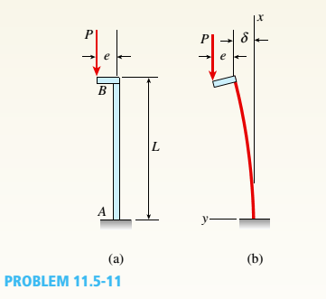
The column shown in the figure is fixed at the base and free at the upper end. A compressive load P acts at the top of the column with an eccentricity e from the axis of the column.
Beginning with the differential equation of the deflection curve, derive formulas for the maximum deflection S of the column and the maximum bending moment Mmaxin the column.
Expert Solution & Answer

Trending nowThis is a popular solution!

Chapter 11 Solutions
Mechanics of Materials (MindTap Course List)
Ch. 11 - A rigid bar of length L is supported by a linear...Ch. 11 - The figure shows an idealized structure consisting...Ch. 11 - -2-3. Two rigid bars are connected with a...Ch. 11 - Repeat Problem 11.2-3 assuming that R= 10 kN ·...Ch. 11 - The figure shows an idealized structure consisting...Ch. 11 - An idealized column consists of rigid bar ABCD...Ch. 11 - An idealized column is made up of rigid segments...Ch. 11 - The figure shows an idealized structure consisting...Ch. 11 - The figure shows an idealized structure consisting...Ch. 11 - The figure shows an idealized structure consisting...
Ch. 11 - The figure shows an idealized structure consisting...Ch. 11 - Rigid column ABCD has an elastic support at B with...Ch. 11 - An idealized column is made up of rigid bars ABC...Ch. 11 - An idealized column is composed of rigid bars ABC...Ch. 11 - Repeat Problem 11.2-14 using L = 12 ft, ß = 0.25...Ch. 11 - An idealized column is composed of rigid bars ABC...Ch. 11 - Column AB has a pin support at A,a roller support...Ch. 11 - Slender column ABC is supported at A and C and is...Ch. 11 - Calculate the critical load PCTfor a W 8 × 35...Ch. 11 - Solve the preceding problem for a W 250 × 89 steel...Ch. 11 - Solve Problem 11.3-3 for a W 10 × 45 steel column...Ch. 11 - A horizontal beam AB is pin-supported at end A and...Ch. 11 - A column ABC is supported at ends A and C and...Ch. 11 - Find the controlling buckling load (kN) for the...Ch. 11 - A column, pinned at top and bottom, is made up of...Ch. 11 - Repeat Problem 11.3-9. Use two C 150 × 12.2 steel...Ch. 11 - A horizontal beam AB is pin-supported at end A and...Ch. 11 - -12 A horizontal beam AB is supported at end A and...Ch. 11 - A horizontal beam AB has a sliding support at end...Ch. 11 - A slender bar AB with pinned ends and length L is...Ch. 11 - A rectangular column with cross-sectional...Ch. 11 - .16 Three identical, solid circular rods, each of...Ch. 11 - Three pinned-end columns of the same material have...Ch. 11 - A long slender column ABC is pinned at ends A and...Ch. 11 - The roof over a concourse at an airport is...Ch. 11 - The hoisting arrangement for lifting a large pipe...Ch. 11 - A pinned-end strut of aluminum (E = 10,400 ksi)...Ch. 11 - The cross section of a column built up of two...Ch. 11 - The truss ABC shown in the figure supports a...Ch. 11 - A truss ABC supports a load W at joint B, as shown...Ch. 11 - An S6 × 12.5 steel cantilever beam AB is supported...Ch. 11 - The plane truss shown in the figure supports...Ch. 11 - A space truss is restrained at joints O, A,B, and...Ch. 11 - A fixed-end column with circular cross section is...Ch. 11 - A cantilever aluminum column has a square tube...Ch. 11 - An aluminum pipe column (E = 10,400 ksi) with a...Ch. 11 - Solve the preceding problem for a steel pipe...Ch. 11 - A wide-flange steel column (E = 30 × l06 psi) of...Ch. 11 - Prob. 11.4.6PCh. 11 - The upper end of a WE × 21 wide-flange steel...Ch. 11 - A vertical post AB is embedded in a concrete...Ch. 11 - The horizontal beam ABC shown in the figure is...Ch. 11 - The roof beams of a warehouse are supported by...Ch. 11 - Determine the critical load Pcrand the equation of...Ch. 11 - A fixed-pinned column is a W310 × 21 steel shape...Ch. 11 - Find the Controlling buckling load (kips) for the...Ch. 11 - Prob. 11.4.14PCh. 11 - A rigid L-shaped frame is supported by a steel...Ch. 11 - An aluminum tube AB with a circular cross section...Ch. 11 - The frame ABC consists of two members AB and BC...Ch. 11 - An aluminum bar having a rectangular cross section...Ch. 11 - ‘11.5-2 A steel bar having a square cross section...Ch. 11 - A simply supported slender column is subjected to...Ch. 11 - A brass bar of a length L = 0.4 m is loaded at end...Ch. 11 - Determine the bending moment M in the pinned-end...Ch. 11 - Plot the load-deflection diagram for a pinned-end...Ch. 11 - Solve the preceding problem for a column with e =...Ch. 11 - A wide-flange member (W200 × 22.5) is compressed...Ch. 11 - A wide-f hinge member (W 10 × 30) is compressed by...Ch. 11 - Solve the preceding problem (W 250 × 44.8) if the...Ch. 11 - The column shown in the figure is fixed at the...Ch. 11 - An aluminum box column with a square cross section...Ch. 11 - Solve the preceding problem for an aluminum column...Ch. 11 - A steel post /t if with a hollow circular cross...Ch. 11 - A frame ABCD is constructed of steel wide-flange...Ch. 11 - A steel bar has a square cross section of width b...Ch. 11 - ]11.6-2 A brass bar (E = 100 GPa) with a square...Ch. 11 - A square aluminum bar with pinned ends carries a...Ch. 11 - A pinned-and column of a length L = 2A m is...Ch. 11 - A pinned-end strut of a length L = 5.2 ft is...Ch. 11 - A circular aluminum tube with pinned ends supports...Ch. 11 - A steel W 12 × 35 column is pin-supported at the...Ch. 11 - A steel W 310 x 52 column is pin-supported at the...Ch. 11 - A steel column (E = 30 x 103 ksi) with pinned ends...Ch. 11 - A W410 × S5 steel column is compressed by a force...Ch. 11 - A steel column ( E = 30 X 103 ksi) that is fixed...Ch. 11 - AW310 × 74 wide-flange steel column with length L...Ch. 11 - A pinned-end column with a length L = 18 ft is...Ch. 11 - The wide-flange, pinned-end column shown in the...Ch. 11 - A W14 × 53 wide-flange column of a length L = 15...Ch. 11 - A wide-flange column with a bracket is fixed at...Ch. 11 - Determine the allowable axial load Pallowa W 10 X...Ch. 11 - Determine the allowable axial load Pallowfor a W...Ch. 11 - Determine the allowable axial load Pallowfor a W...Ch. 11 - Select a steel wide-flange column of a nominal...Ch. 11 - Prob. 11.9.5PCh. 11 - Select a steel wide-flange column of a nominal...Ch. 11 - Prob. 11.9.7PCh. 11 - Determine the allowable axial load Pallowfor a...Ch. 11 - Determine the allowable axial load Pallowfor a...Ch. 11 - Determine the allowable axial load Pallowfor a...Ch. 11 - -11 Determine the maximum permissible length...Ch. 11 - Determine the maximum permissible length Lmaxfor a...Ch. 11 - A steel pipe column with pinned ends supports an...Ch. 11 - The steel columns used in a college recreation...Ch. 11 - A W8 × 28 steel wide-flange column with pinned...Ch. 11 - Prob. 11.9.16PCh. 11 - Prob. 11.9.17PCh. 11 - Prob. 11.9.18PCh. 11 - Prob. 11.9.19PCh. 11 - Prob. 11.9.20PCh. 11 - Prob. 11.9.21PCh. 11 - An aluminum pipe column (alloy 2014-T6) with...Ch. 11 - Prob. 11.9.23PCh. 11 - Prob. 11.9.24PCh. 11 - Prob. 11.9.25PCh. 11 - Prob. 11.9.26PCh. 11 - Prob. 11.9.27PCh. 11 - Prob. 11.9.28PCh. 11 - Prob. 11.9.29PCh. 11 - Prob. 11.9.30PCh. 11 - A wood column with, a rectangular cross section...Ch. 11 - Prob. 11.9.32PCh. 11 - Prob. 11.9.33PCh. 11 - A square wood column with side dimensions b (see...Ch. 11 - A square wood column with side dimensions b (see...Ch. 11 - Prob. 11.9.36P
Knowledge Booster


Learn more about
Need a deep-dive on the concept behind this application? Look no further. Learn more about this topic, mechanical-engineering and related others by exploring similar questions and additional content below.Similar questions
- A horizontal beam AB has a sliding support at end A and carries a load Q at end B, as shown in the figure part a. The beam is supported at C and D by two identical pinned-end columns of length L. Each column has flexural rigidity EI. Find an expression for the critical load QCT. (In other words, at what load Qcrdoes the system collapse because of Eu 1er buckling of the columns?) Repeat part (a), but assume a pin support at A. Find an expression for the critical moment Mcr(i.e., find the moment M at B at which the system collapses because of Euler buckling of the columns).arrow_forwardTwo pipe columns (AB, FC) are pin-connected to a rigid beam (BCD), as shown in the figure. Each pipe column has a modulus of E, but heights (L1or L2) and outer diameters (d1or different for each column. Assume the inner diameter of each column is 3/4 of outer diameter. Uniformly distributed downward load q = 2PIL is applied over a distance of 3L/4 along BC, and concentrated load PIA is applied downward at D. (a) Derive a formula for the displacementarrow_forwardA steel post (E=30×106) having thickness t = 1/8 in. and height L = 72 in. support a stop sign (see figure), where s = 12.5 in. The height of the post L is measured from the base to the centroid of the sign. The stop sign is subjected to wind pressure p = 20 lb/ft2 normal to its surface. Assume that the post is fixed at its base. What is the resultant load on the sign? (Sec Appendix E, Case 25, for properties of an octagon, n =8.) What is the maximum bending stress in the post? Repeat part (b) if the circular cut-outs arc eliminated over the height of the post.arrow_forward
- An overhanging beam ABC with flexural rigidity EI = 15 kip-in" is supported by a sliding support at A and by a spring of stiffness k at point fi(see figure). Span AB has a length L = 30 in. and carries a u ni form load. The overhang BC has a length b = 15 in. For what stiffness k of the spring will the uniform load produce no deflection at the free end C?arrow_forward-12 A horizontal beam AB is supported at end A and carries a load Q at joint B, as shown in the figure part a. The beam is also supported at C by a pinned-end column of length L. The column has flexural rigidity EI. For the case of a sliding support at A (figure part a), what is the critical load Qcr? (In other words, at what load QCTdoes the system collapse because of Euler buckling of the column DC?) Repeat part (a) if the sliding support at A is replaced by column AF with a length 3L/2 and flexural rigidity EI (see figure part b).arrow_forwardA weight W = 4500 lb falls from a height h onto a vertical wood pole having length L = 15 ft, diameter d = 12 in., and modulus of elasticity E = 1.6 × 10⁶ psi (see figure). If the allowable stress in the wood under an impact load is 2500 psi. what is the maximum permissible height h?arrow_forward
- A simply supported slender column is subjected to axial load P = 175 kips applied at distance e = 0,5 in. from joint s A and B (see figure). The column has a circular cross section with an outer diameter of 10 in. and wall thickness of 0.5 in. Calculate the height of the column if the maximum deflection caused by the axial loads is 0,1 in. Assume that E = 29,000 ksi.arrow_forwardA column ABC is supported at ends A and C and compressed by an axial load P (figure a). Lateral support is provided at point B but only in the plane of the figure; lateral support perpendicular to the plane of the figure is provided only at A and C. The column is constructed of two channel sections (C 6 × 8.2) back to back (see figure b). The modulus of elasticity of the column is E = 29,500 ksi and the proportional limit is 50 ksi. The height of the column is L = 15 ft. Find the allowable value of load P using a factor of safety of 2.5.arrow_forward-4-4 A cantilever beam is supported at B by cable BC. The beam carries a uniform load q = 200 N/M. If the length of the beam is L = 3 m, find the force in the cable and the reactions at A. Ignore the axial flexibility of the cable.arrow_forward
- A steel beam ABC is simply supported at A and held by a high-strength steel wire at B (see figure). A load P = 240 lb acts at the free end C. The wire has axial rigidity EA = 1500 x 103 lb, and the beam has flexural rigidity EI = 36 X 106 lb-in". What is the deflectionarrow_forwardA cantileverbeam^Cßsupportstwo concentrated loads Ptand A, as shown in the figure. Calculate the deflections SBand 8Cat points B and C, respectively. Assume Px= 10 kN, P\ = 5 kN, L = 2.6 m, E = 200 GPa, and / = 20.1 x I0ft mm4.arrow_forwardB cams AB and CDE are connected using rigid link DB with hinges (or moment releases) at ends D and B (see figure a). Beam AB is fixed at joint A and beam CDE is pin-supported at joint E. Load P = 150 lb is applied at C\ Calculate the deflections of joints B and joint C Assume L = 9 ft and EI = 127,000 kip-in2. Repeat part (a) if rigid link DB is replaced by a linear spring with k = 20 kips/in (see figure b).arrow_forward
arrow_back_ios
SEE MORE QUESTIONS
arrow_forward_ios
Recommended textbooks for you
 Mechanics of Materials (MindTap Course List)Mechanical EngineeringISBN:9781337093347Author:Barry J. Goodno, James M. GerePublisher:Cengage Learning
Mechanics of Materials (MindTap Course List)
Mechanical Engineering
ISBN:9781337093347
Author:Barry J. Goodno, James M. Gere
Publisher:Cengage Learning
Column buckling; Author: Amber Book;https://www.youtube.com/watch?v=AvvaCi_Nn94;License: Standard Youtube License