
Mechanics of Materials (MindTap Course List)
9th Edition
ISBN: 9781337093347
Author: Barry J. Goodno, James M. Gere
Publisher: Cengage Learning
expand_more
expand_more
format_list_bulleted
Videos
Textbook Question
Chapter 11, Problem 11.5.1P
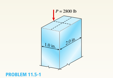
An aluminum bar having a rectangular cross section (2.0 in. × 1.0 in.) and length L = 30 in. is compressed by axial loads that have a resultant P = 2800 lb acting at the midpoint of the long side of the cross section (sec figure).
Assuming that the modulus of elasticity E is equal to 10 × 106 psi and that the ends of the bar are pinned, calculate the maximum deflection
Expert Solution & Answer
Want to see the full answer?
Check out a sample textbook solution
Chapter 11 Solutions
Mechanics of Materials (MindTap Course List)
Ch. 11 - A rigid bar of length L is supported by a linear...Ch. 11 - The figure shows an idealized structure consisting...Ch. 11 - -2-3. Two rigid bars are connected with a...Ch. 11 - Repeat Problem 11.2-3 assuming that R= 10 kN ·...Ch. 11 - The figure shows an idealized structure consisting...Ch. 11 - An idealized column consists of rigid bar ABCD...Ch. 11 - An idealized column is made up of rigid segments...Ch. 11 - The figure shows an idealized structure consisting...Ch. 11 - The figure shows an idealized structure consisting...Ch. 11 - The figure shows an idealized structure consisting...
Ch. 11 - The figure shows an idealized structure consisting...Ch. 11 - Rigid column ABCD has an elastic support at B with...Ch. 11 - An idealized column is made up of rigid bars ABC...Ch. 11 - An idealized column is composed of rigid bars ABC...Ch. 11 - Repeat Problem 11.2-14 using L = 12 ft, ß = 0.25...Ch. 11 - An idealized column is composed of rigid bars ABC...Ch. 11 - Column AB has a pin support at A,a roller support...Ch. 11 - Slender column ABC is supported at A and C and is...Ch. 11 - Calculate the critical load PCTfor a W 8 × 35...Ch. 11 - Solve the preceding problem for a W 250 × 89 steel...Ch. 11 - Solve Problem 11.3-3 for a W 10 × 45 steel column...Ch. 11 - A horizontal beam AB is pin-supported at end A and...Ch. 11 - A column ABC is supported at ends A and C and...Ch. 11 - Find the controlling buckling load (kN) for the...Ch. 11 - A column, pinned at top and bottom, is made up of...Ch. 11 - Repeat Problem 11.3-9. Use two C 150 × 12.2 steel...Ch. 11 - A horizontal beam AB is pin-supported at end A and...Ch. 11 - -12 A horizontal beam AB is supported at end A and...Ch. 11 - A horizontal beam AB has a sliding support at end...Ch. 11 - A slender bar AB with pinned ends and length L is...Ch. 11 - A rectangular column with cross-sectional...Ch. 11 - .16 Three identical, solid circular rods, each of...Ch. 11 - Three pinned-end columns of the same material have...Ch. 11 - A long slender column ABC is pinned at ends A and...Ch. 11 - The roof over a concourse at an airport is...Ch. 11 - The hoisting arrangement for lifting a large pipe...Ch. 11 - A pinned-end strut of aluminum (E = 10,400 ksi)...Ch. 11 - The cross section of a column built up of two...Ch. 11 - The truss ABC shown in the figure supports a...Ch. 11 - A truss ABC supports a load W at joint B, as shown...Ch. 11 - An S6 × 12.5 steel cantilever beam AB is supported...Ch. 11 - The plane truss shown in the figure supports...Ch. 11 - A space truss is restrained at joints O, A,B, and...Ch. 11 - A fixed-end column with circular cross section is...Ch. 11 - A cantilever aluminum column has a square tube...Ch. 11 - An aluminum pipe column (E = 10,400 ksi) with a...Ch. 11 - Solve the preceding problem for a steel pipe...Ch. 11 - A wide-flange steel column (E = 30 × l06 psi) of...Ch. 11 - Prob. 11.4.6PCh. 11 - The upper end of a WE × 21 wide-flange steel...Ch. 11 - A vertical post AB is embedded in a concrete...Ch. 11 - The horizontal beam ABC shown in the figure is...Ch. 11 - The roof beams of a warehouse are supported by...Ch. 11 - Determine the critical load Pcrand the equation of...Ch. 11 - A fixed-pinned column is a W310 × 21 steel shape...Ch. 11 - Find the Controlling buckling load (kips) for the...Ch. 11 - Prob. 11.4.14PCh. 11 - A rigid L-shaped frame is supported by a steel...Ch. 11 - An aluminum tube AB with a circular cross section...Ch. 11 - The frame ABC consists of two members AB and BC...Ch. 11 - An aluminum bar having a rectangular cross section...Ch. 11 - ‘11.5-2 A steel bar having a square cross section...Ch. 11 - A simply supported slender column is subjected to...Ch. 11 - A brass bar of a length L = 0.4 m is loaded at end...Ch. 11 - Determine the bending moment M in the pinned-end...Ch. 11 - Plot the load-deflection diagram for a pinned-end...Ch. 11 - Solve the preceding problem for a column with e =...Ch. 11 - A wide-flange member (W200 × 22.5) is compressed...Ch. 11 - A wide-f hinge member (W 10 × 30) is compressed by...Ch. 11 - Solve the preceding problem (W 250 × 44.8) if the...Ch. 11 - The column shown in the figure is fixed at the...Ch. 11 - An aluminum box column with a square cross section...Ch. 11 - Solve the preceding problem for an aluminum column...Ch. 11 - A steel post /t if with a hollow circular cross...Ch. 11 - A frame ABCD is constructed of steel wide-flange...Ch. 11 - A steel bar has a square cross section of width b...Ch. 11 - ]11.6-2 A brass bar (E = 100 GPa) with a square...Ch. 11 - A square aluminum bar with pinned ends carries a...Ch. 11 - A pinned-and column of a length L = 2A m is...Ch. 11 - A pinned-end strut of a length L = 5.2 ft is...Ch. 11 - A circular aluminum tube with pinned ends supports...Ch. 11 - A steel W 12 × 35 column is pin-supported at the...Ch. 11 - A steel W 310 x 52 column is pin-supported at the...Ch. 11 - A steel column (E = 30 x 103 ksi) with pinned ends...Ch. 11 - A W410 × S5 steel column is compressed by a force...Ch. 11 - A steel column ( E = 30 X 103 ksi) that is fixed...Ch. 11 - AW310 × 74 wide-flange steel column with length L...Ch. 11 - A pinned-end column with a length L = 18 ft is...Ch. 11 - The wide-flange, pinned-end column shown in the...Ch. 11 - A W14 × 53 wide-flange column of a length L = 15...Ch. 11 - A wide-flange column with a bracket is fixed at...Ch. 11 - Determine the allowable axial load Pallowa W 10 X...Ch. 11 - Determine the allowable axial load Pallowfor a W...Ch. 11 - Determine the allowable axial load Pallowfor a W...Ch. 11 - Select a steel wide-flange column of a nominal...Ch. 11 - Prob. 11.9.5PCh. 11 - Select a steel wide-flange column of a nominal...Ch. 11 - Prob. 11.9.7PCh. 11 - Determine the allowable axial load Pallowfor a...Ch. 11 - Determine the allowable axial load Pallowfor a...Ch. 11 - Determine the allowable axial load Pallowfor a...Ch. 11 - -11 Determine the maximum permissible length...Ch. 11 - Determine the maximum permissible length Lmaxfor a...Ch. 11 - A steel pipe column with pinned ends supports an...Ch. 11 - The steel columns used in a college recreation...Ch. 11 - A W8 × 28 steel wide-flange column with pinned...Ch. 11 - Prob. 11.9.16PCh. 11 - Prob. 11.9.17PCh. 11 - Prob. 11.9.18PCh. 11 - Prob. 11.9.19PCh. 11 - Prob. 11.9.20PCh. 11 - Prob. 11.9.21PCh. 11 - An aluminum pipe column (alloy 2014-T6) with...Ch. 11 - Prob. 11.9.23PCh. 11 - Prob. 11.9.24PCh. 11 - Prob. 11.9.25PCh. 11 - Prob. 11.9.26PCh. 11 - Prob. 11.9.27PCh. 11 - Prob. 11.9.28PCh. 11 - Prob. 11.9.29PCh. 11 - Prob. 11.9.30PCh. 11 - A wood column with, a rectangular cross section...Ch. 11 - Prob. 11.9.32PCh. 11 - Prob. 11.9.33PCh. 11 - A square wood column with side dimensions b (see...Ch. 11 - A square wood column with side dimensions b (see...Ch. 11 - Prob. 11.9.36P
Knowledge Booster


Learn more about
Need a deep-dive on the concept behind this application? Look no further. Learn more about this topic, mechanical-engineering and related others by exploring similar questions and additional content below.Similar questions
- A weight W = 4500 lb falls from a height h onto a vertical wood pole having length L = 15 ft, diameter d = 12 in., and modulus of elasticity E = 1.6 × 10⁶ psi (see figure). If the allowable stress in the wood under an impact load is 2500 psi. what is the maximum permissible height h?arrow_forwardA simple beam that is 18 ft long supports a uniform load of intensity q. The beam is constructed of two C8 x 11.5 sections (channel sections or C-shapes) on either side of a 4 × 8 (actual dimensions) wood beam (see the cross section shown in the figure part a). The modulus of elasticity of the steel (E; = 30,000 ksi) is 20 times that of the wood (Ew). (a) If the allowable stresses in the steel and wood are 12,000 psi and 900 psi, respectively, what is the allowable load qmax Note: Disregard the weight of the beam, and see Table F-3(a) of Appendix F for the dimensions and properties of the C-shape beam. (b) If the beam is rotated 90° to bend about its v axis (see figure part b) and uniform load q = 250 lb/ft is applied, find the maximum stresses trs and crw in the steel and wood, respectively Include the weight of the beam. (Assume weight densities of 35 lb/ft3 and 490 lb/ft3 for the wood and steel, respectively.)arrow_forward-14 A simply supported composite beam with a 3.6 m span supports a triangularly distributed load of peak intensity q0at mid-span (see figure part a). The beam is constructed of two wood joists, each 50 mm x 280 mm, fastened to two steel plates, one of dimensions 6 mm × 80 mm and the lower plate of dimensions 6 mm x 120mm (see figure part b). The modulus of elasticity for the wood is 11 GPa and for the steel is 210 GPa. If the allowable stresses are 7 MPa for the wood and 120 MPa for the steel, find the allowable peak load intensity q0maxwhen the beam is bent about the z axis. Neglect the weight of the beam.arrow_forward
- A r o lukI f/frm f «m t ub e of ou t sid e d ia met er ^ and a copper core of diameter dxare bonded to form a composite beam, as shown in the figure, (a) Derive formulas for the allowable bending moment M that can be carried by the beam based upon an allowable stress <7Ti in the titanium and an allowable stress (u in the copper (Assume that the moduli of elasticity for the titanium and copper are Er- and £Cu, respectively.) (b) If d1= 40 mm, d{= 36 mm, ETl= 120 GPa, ECu= 110 GPa, o-Ti = 840 MPa, and ctqj = 700 MPa, what is the maximum bending moment Ml (c) What new value of copper diameter dtwill result in a balanced design? (i.e., a balanced design is that in which titanium and copper reach allow- able stress values at the same time).arrow_forwardA beam with a guided support and 10-ft span supports a distributed load of intensity q = 660 lb/ft over its first half (see figure part a) and a moment Mq = 300 ft-lb at joint B. The beam consists of a wood member (nominal dimensions 6 in. x 12 in. and actual dimensions 5.5 in. x 11.5 in. in cross section, as shown in the figure part b) that is reinforced by 0.25-in.-thick steel plates on top and bottom. The moduli of elasticity for the steel and wood are £s = 30 X 106 psi and £"w = 1.5 X 10⁶ psi, respectively. Calculate the maximum bending stresses trs in the steel plates and rw in the wood member due to the applied loads. If the allowable bending stress in the steel plates is = 14,000 psi and that in the wood is (T.dV!= 900 psi, find qmiiX. (Assume that the moment at .fi, A/0, remains at 300 ft-lb.) If q = 660 lb/ft and allowable stress values in part (b) apply, what is Müm^ at B?arrow_forwardThe cantilever beam AB shown in the figure is an S6 × 12.5 steel I-beam with E = 30 × 106 psi. The simple beam DE is a wood beam 4 in. x 12 in. (nominal dimensions) in cross section with E = 1.5 x 10⁶ psi. A steel rod AC of diameter 0.25 in., length 10 ft, and E = 30 x 106 psi serves as a hanger joining the two beams. The hanger fits snugly between the beams before the uniform load is applied to beam DE. Determine the tensile force Fin the hanger and the maximum bending moments MABand MDEin the two beams due to the uniform load, which has an intensity q = 400 lb/ft. Hint: To aid in obtaining the maximum bending moment in beam DE, draw the shear-force and bending-moment diagrams.arrow_forward
- A wood beam with cross-sectional dimensions 200 mm x 300 mm is reinforced on its sides by steel plates 12 mm thick (see figure). The moduli of elasticity for the steel and wood are E±= 190 GPa and Ew= 11 GPa, respectively. Also, the corresponding allowable stresses are eS= 110 MPa and ew = 7.5 MPa, (a) Calculate the maximum permissible bending moment Mmaxwhen the beam is bent about the- axis. Repeat part (a) if the beam is now bent about its y axis. Find the required thickness of the steel plates on the beam bent about the y axis so that Mmaxis the same for both beam orientations.arrow_forwardA uniformly loaded, steel wide-flange beam with simple supports (see figure) has a downward deflection of 10 mm at the midpoint and angles of rotation equal to 0.01 radians at the ends. Calculate the height h of the beam if the maximum bending stress is 90 MPa and the modulus of elasticity is 200 GPa, (Use the formulas of Example 9-L)arrow_forwardA fixed-end beam is loaded by a uniform load q = 15 kN/m and a point load P = 30 kN at mid-span. The beam has a length of 4 m and modulus of elasticity of 205 GPa. Find reactions at A and B. Calculate the height of the beam if the displacement at mid-span is known to be 3 mm. Assume that the beam has rectangular cross section with h/b = 2.arrow_forward
- A simply supported wooden I-beam with a 12-ft span supports a distributed load of intensity q = 90 lb/ft over its length (see figure part a). The beam is constructed with a web of Douglas-fir plywood and flanges of pine glued to the web, as shown in the figure part b. The plywood is 3/8 in. thick: the flanges are 2 in, × 2 in, (actual size). The modulus of elasticity for the plywood is 1,600,000 psi and for the pine is 1,200,000 psL Calculate the maximum bending stresses in the pine flanges and in the plywood web. What is q, if allowable stresses are 1600 psi in the flanges and 1200 psi in the web?arrow_forwardA simple beam of span length 3.2 m carries a uniform load of intensity 48 kN/m, The cross section of the beam is a hollow box with wood flanges and steel side plates, as shown in the figure. The wood flanges are 75 mm x 100 mm in cross section, and the steel plates are 300 mm deep. What is the required thickness t of the steel plates if the allowable stresses are 120 M Pa for the steel and 6,5 M Pa for the wood? (Assume that the moduli of elasticity for the steel and wood are 210 GPa and 10 GPa, respectively, and disregard the weight of the beam.)arrow_forwardBeam ABCD represents a reinforced-concrete foundation beam that supports a uniform load of intensity q1= 3500 lb/ft (see figure). Assume that the soil pressure on the underside of the beam is uniformly distributed with intensity q2 Find the shear force VBand bending moment MBat point B. Find the shear force Vmand bending moment M at the midpoint of the beam.arrow_forward
arrow_back_ios
SEE MORE QUESTIONS
arrow_forward_ios
Recommended textbooks for you
 Mechanics of Materials (MindTap Course List)Mechanical EngineeringISBN:9781337093347Author:Barry J. Goodno, James M. GerePublisher:Cengage Learning
Mechanics of Materials (MindTap Course List)
Mechanical Engineering
ISBN:9781337093347
Author:Barry J. Goodno, James M. Gere
Publisher:Cengage Learning
Mechanics of Materials Lecture: Beam Design; Author: UWMC Engineering;https://www.youtube.com/watch?v=-wVs5pvQPm4;License: Standard Youtube License