
Videos
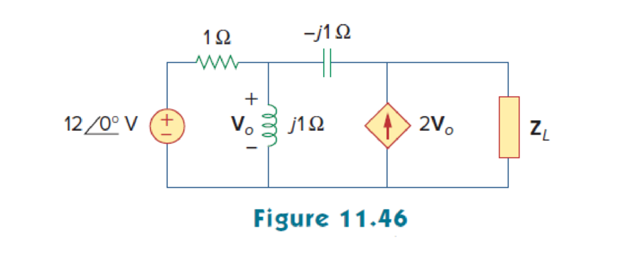
In the circuit of Fig. 11.46, find the value of ZL that will absorb the maximum power and the value of the maximum power.
Find the value of the load impedance
Answer to Problem 15P
The value of load impedance
Explanation of Solution
Given data:
Refer to Figure 11.46 in the textbook.
The inductance
The capacitance C is
The source voltage is
Formula used:
Write the expression to find the maximum average power.
Here,
Write the general expression for load impedance
Calculation:
Refer to Figure 11.46 in the textbook.
In the circuit, to calculate the Thevenin impedance
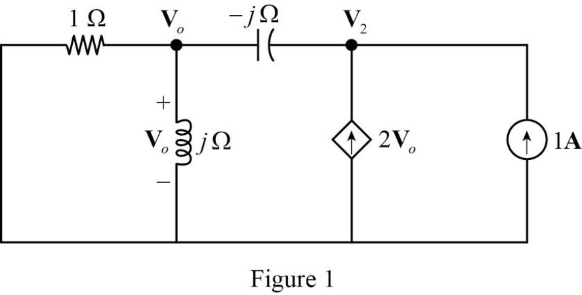
In Figure 1, apply Kirchhoff’s currrent law at node voltage
Rearrange the equation as follows,
In Figure 1, apply Kirchhoff’s currrent law at node voltage
Rearrange the equation as follows,
Substitute equation (3) in equation (4) to find
Rearrange the equation as follows,
The Thevenin impedance is,
Substitute
Simplify the equation as follows,
For maximum average power transfer, the load impedance
On comparing the equation with equation (2),
The given circuit of Figure 11.46 is modified as shown in Figure 2.
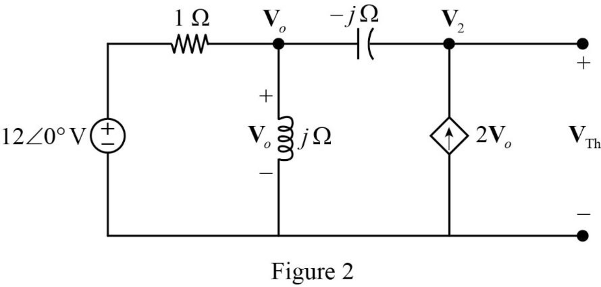
In Figure 2, apply Kirchhoff’s current law at node voltage
Rearrange the equation as follows,
In Figure 2, apply Kirchhoff’current law at node voltage
Rearrange the equation as follows,
Substitute
The voltage
Convert the equation from rectangular to polar form.
The Thevenin voltage,
Substitute
Conclusion:
Thus, The value of load impedance
Want to see more full solutions like this?
Chapter 11 Solutions
Fundamentals of Electric Circuits
Additional Engineering Textbook Solutions
Microelectronics: Circuit Analysis and Design
Basic Engineering Circuit Analysis
Electric Circuits (10th Edition)
Fundamentals of Applied Electromagnetics (7th Edition)
Introductory Circuit Analysis (13th Edition)
Loose Leaf for Engineering Circuit Analysis Format: Loose-leaf


- A load of 500 kVA operates at 0.6 lagging power factor on 1100 V, 50 Hz mains. The power factor of the system is improved from 0.6 lagging to 0.95 lagging by using a capacitor bank connected in delta. Assuming the KVA of the load remains constant, indicate the rating of the capacitor and find how much additional kW can be obtained.arrow_forwardA load of 500 kVA operates on 1100 V, 50 Hz mains with power factor of 0.6 lagging. It is required to improve the power factor to 0.95 lagging by using the star connected capacitor bank. Assuming that the load KVA remains constant, suggest the rating of the capacitors.arrow_forwarda power station has a connected load of 48MW. the energy generated for the year is 61500MWh. if the station has a load factor of 35%. solve the demand factor of the station. Subject: Distribution System and Substation Designarrow_forward
- . A power station has a connected load of 48 MW. The energy generated for the year is 61,500 MWh. If the station has a load factor of 35%, solve the demand factor of the station. Answer: 0.4179 or 41.79% Subject: Distribution System and Substation Designarrow_forwardA load of 500 kVA operates at 0.6 lagging power factor on 1100V, 50 Hz mains. The power factor of the system is improved from 0.6 lagging to 0.95 lagging by using a delta connected capacitor bank. Assuming VA of the load remains constant, indicate the rating of the capacitor and find the additional kW that can be obtained.arrow_forwardThree coils each having resistance 6 and inductance are connected in star with 415V. If the line current is 30 A: a) find the value of inductive reactance as well as inductance value? B) If θ = 45 then calculate the power dissipation in kW when it is connected in Delta.arrow_forward
- A factory take 500kW at 0.75 pf lagging from a constant voltage AC supply. A synchronous condenser with negligible losses is connected to the factory to improve the power factor to 0.95 lagging. find the kVAR of the synchronous condenser.arrow_forwardThe power factor of a certain load is improved to 0.92 lagging with the addition of a 30 kVAR bank of capacitors. If the resulting supply apparent power is 200 kVA, determine the power factor before correction.arrow_forwardWhen drawing three-phase inductive 250 kW from the 440 V transmission line, the power coefficient is 0.707. When a three-phase parallel 60 kVAR capacitor group is connected to this load, find the current drawn from the line and the power coefficient?arrow_forward
- If an AC motor with impedance ZL= 4.2+j3.6 ohm is supplied by 220 vrm, 60HZ source. Find the p.f, pav, and Q.arrow_forwardCompare and contrast diesel power plant with one of the existing power plant in the country in terms of: a. Efficiencyarrow_forwardThe impedance of an electrical circuit is (30 − j50) ohms. Determine (a) the resistance, (b) the capacitance, (c) the modulus of the impedance, and (d) the current flowing and its phase angle, when the circuit is connected to a 240V, 50 Hz supply.arrow_forward
 Introductory Circuit Analysis (13th Edition)Electrical EngineeringISBN:9780133923605Author:Robert L. BoylestadPublisher:PEARSON
 Delmar's Standard Textbook Of ElectricityElectrical EngineeringISBN:9781337900348Author:Stephen L. HermanPublisher:Cengage Learning
 Programmable Logic ControllersElectrical EngineeringISBN:9780073373843Author:Frank D. PetruzellaPublisher:McGraw-Hill Education
 Fundamentals of Electric CircuitsElectrical EngineeringISBN:9780078028229Author:Charles K Alexander, Matthew SadikuPublisher:McGraw-Hill Education
 Electric Circuits. (11th Edition)Electrical EngineeringISBN:9780134746968Author:James W. Nilsson, Susan RiedelPublisher:PEARSON
 Engineering ElectromagneticsElectrical EngineeringISBN:9780078028151Author:Hayt, William H. (william Hart), Jr, BUCK, John A.Publisher:Mcgraw-hill Education,