
Videos
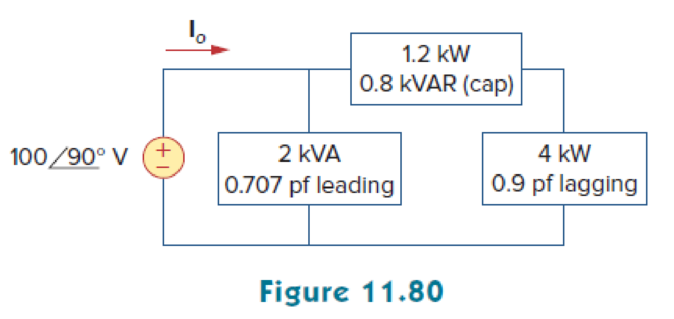
Given the circuit in Fig. 11.80, find Io and the overall complex power supplied.
Calculate the current
Answer to Problem 61P
The current
Explanation of Solution
Given data:
Refer to Figure 11.80 in the textbook.
The current
For load A,
The apparent power
The power factor
For load B,
The real power
The real power
For load C,
The real power
The power factor
Formula used:
Write the expression to find the complex power.
Here,
Write the expression to find the power factor
Here,
Write the expression to find the real power.
Write the expression to find the reactive power.
Write the expression to find the output voltage.
Calculation:
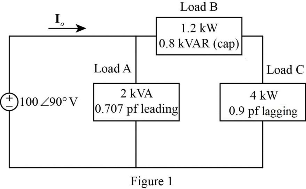
The given Figure 11.80 is redrawn as shown in Figure 1.
For load A:
Substitute
Substitute
Substitute
Substitute
As the power factor is leading, the load is capacitive. Therefore, the equation becomes,
For load B:
Substitute
As the load is capacitive, the power factor is leading. Therefore, the equation becomes,
For load C:
Substitute
Substitute
Rearrange the equation as follows,
Substitute
Substitute
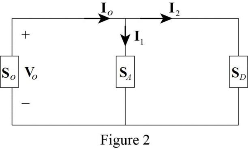
In Figure 1, the load B and load C are connected in series. Therefore,
Substitute
The modified Figure is shown in Figure 2.
Substitute
Substitute
Apply Kirchhoff’s current law in Figure 2 to find the current
Substitute
Convert the equation from rectangular to polar form.
The overall complex power supplied by the source is,
Substitute
Conclusion:
Thus, the current
Want to see more full solutions like this?
Chapter 11 Solutions
Fundamentals of Electric Circuits


- Given a tee connected system with power factor of 80 percent and true power of 2,500 kW. Calculate the reactive power.arrow_forwardA generator is supplying a load of 700 kW at a power factor of 0.9 lagging. If the power factor is raised to unity, how many more kilowatts can alternator supply for the same kVA loading?arrow_forwardA load of 500 kVA operates at 0.6 lagging power factor on 1100 V, 50 Hz mains. The power factor of the system is improved from 0.6 lagging to 0.95 lagging by using a capacitor bank connected in delta. Assuming the KVA of the load remains constant, indicate the rating of the capacitor and find how much additional kW can be obtained.arrow_forward
- A 132MW generator sends power to an industrial load at 132kV, 500A, Unity power factor. Excluding all losses, the effiency is :arrow_forwardcalculate the voltages of the secondary windings of each of the transformers. calculate the average power (p/2), which is delivered to each of the four resistors.arrow_forwardA series generator delivers a power of 6.25kW and a load resistance of25Ω. If RA=0.05Ω and RS=0.025Ω, calculate the generated emf.arrow_forward
- the power factor of a certain load is connected to 0.9 lagging with the addition of 20 kvar of capacitors. If the final kva is 185, determine the power triangle of the load before correction.arrow_forwardTwo alternators operating in parallel supply the following loads: A = 400W, unity pf; B=1000kW, 0.707 pf lagging C = 600 kW, 0.9 leading pf. One machine supplies 800kW at 0.866 lagging power factor. What is the power factor of the other machine?arrow_forwardThe impedance of an electrical circuit is (30 − j50) ohms. Determine (a) the resistance, (b) the capacitance, (c) the modulus of the impedance, and (d) the current flowing and its phase angle, when the circuit is connected to a 240V, 50 Hz supply.arrow_forward
- A series circuit containing a noninductive resistance of 3 Ω and a coil is connected to a 120 V, 60 Hz supply. The current is 25 A. The true power, as indicated by a wattmeter, is 2500 W. Determine: the power factor of the series circuit. the effective resistance of the coil. the impedance and inductive rea ctance for the coil. the power factor of the coilarrow_forwardAn alternator is supplying a load of 300 kW at a power factor of 0.6 lagging. If the power factor is raised to unity, how many more kW can alternator supply ?arrow_forwardIt is desired to correct the 2,400-kVa 0.65 lagging power factor load in a plantto unity by the installation of a synchronous condenser. Calculate the kilovoltampere rating of the latter. Ans.: 1824 kVAarrow_forward
 Power System Analysis and Design (MindTap Course ...Electrical EngineeringISBN:9781305632134Author:J. Duncan Glover, Thomas Overbye, Mulukutla S. SarmaPublisher:Cengage Learning