
Videos
(a)
The cooling load and the COP.
(a)
Answer to Problem 32P
The cooling load and the COP is
Explanation of Solution
Show the T-s diagram for ideal vapor-compression refrigeration cycle as in Figure (1).
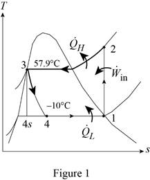
From Figure (1), write the specific enthalpy at state 3 is equal to state 4 due to throttling process.
Here, specific enthalpy at state 3 is
Express the heat removed from the cooled space.
Here, specific enthalpy at state 1, 3 and 4 is
Express heat supplied to the cooled space.
Here, specific enthalpy at state 2 is
Express the work input.
Express the COP of the cycle.
Express pressure at state 2 and state 3.
Here, pressure at state 2 and 3 is
Express quality at state 4.
Here, specific enthalpy at saturated liquid and evaporation and
Express specific entropy at state 4.
Here, specific entropy at saturated liquid and evaporation and
Conclusion:
Refer Table A-11, “saturated refrigerant-134a-temperature table”, and write the properties corresponding to initial temperature of
Here, specific entropy at state 1 is
Refer Table A-11, “saturated refrigerant-134a-tempertaure table”, and write the pressure state 2 and 3 corresponding to temperature of
Write the formula of interpolation method of two variables.
Here, the variables denote by x and y is temperature and saturated pressure respectively.
Show the saturated pressure corresponding to temperature as in Table (1).
|
Temperature |
Saturated pressure |
| 56 | 1529.1 |
| 57.9 | |
| 60 | 1682.8 |
Substitute
Substitute
Perform unit conversion of pressure at state 2 from
Refer Table A-13, “superheated refrigerant 134a”, and write the specific enthalpy at state 2 corresponding to pressure at state 2 of
Show the specific enthalpy at state 2 corresponding to specific entropy as in Table (2).
|
Specific entropy at state 2 |
Specific enthalpy at state 2 |
| 0.9164 | 280.71 |
| 0.9378 | |
| 0.9536 | 293.27 |
Use excels and substitutes the value from Table (2) in Equation (VIII) to obtain the specific enthalpy at state 2.
Refer Table A-12, “saturated refrigerant 134a-pressure table”, and write the properties corresponding to pressure at state 3 of
Here, specific enthalpy and entropy at saturated liquid is
Refer Table A-11, “saturated refrigerant-134a-tempertaure table”, and write the properties corresponding to temperature of
Substitute
Substitute
Here, specific entropy at state 4 is
Substitute
Hence, the cooling load is
Substitute
Substitute
Substitute
Hence, the COP of the cycle is
(b)
The exergy destruction in each component of the cycle and the total exergy destruction in the cycle.
(b)
Answer to Problem 32P
The exergy destruction in compressor is
Explanation of Solution
For compressor:
Express the exergy destruction in compressor.
Here, surrounding temperature is
For condenser:
Express the exergy destruction in condenser.
Here, entropy generation during process 2-3 is
For expansion valve:
For evaporator:
Express the exergy destruction in evaporator.
Here, entropy generation during process 4-1 is
Express the total exergy destruction in the cycle.
Conclusion:
Perform unit conversion of surrounding temperature from
Perform unit conversion of high temperature medium from
Perform unit conversion of low temperature medium from
Substitute
Hence, the exergy destruction in compressor is
Substitute
Hence, the exergy destruction in condenser is
Substitute
Hence, the exergy destruction in expansion valve is
Substitute
Hence, the exergy destruction in evaporator is
Substitute
Hence, the total exergy destruction in the cycle is
(c)
The second-law efficiency of the compressor, the evaporator, and the cycle.
(c)
Answer to Problem 32P
The second-law efficiency of the compressor is
Explanation of Solution
Express the exergy of the heat transferred from the low temperature medium.
Determine the second law efficiency of the cycle.
Express the total exergy destruction in the cycle.
Express the second law efficiency of the compressor.
Here, rate of work done on reversible process is
Express the exergy difference in evaporator.
Here, rate of exergy difference during process 1-4 is
Express the second law efficiency of the evaporator.
Conclusion:
Substitute
Substitute
Hence, the second-law efficiency of the cycle is
Substitute
Substitute
Hence, the second-law efficiency of the compressor is
Substitute
Substitute
Hence, the second-law efficiency of the evaporator is
Want to see more full solutions like this?
Chapter 11 Solutions
Thermodynamics: An Engineering Approach


- The operating condition for the single compressor in a household refrigerator is the lowest box temperature, which is typically A. 0F B. -20F C. 20F D. 40Farrow_forwardConsider a refrigeration system using refrigerant-134a as the working fluid. If this refrigerator is to operate in an environment at 20°C, what is the minimum pressure to which the refrigerant should be compressed? Why?arrow_forwardConsider a refrigeration system that operates on an actual vapor-compression refrigeration cycle with refrigerant 134a as the working fluid with an isentropic efficiency of a compressor of 75.1%. The refrigerant enters the compressor as saturated vapor at 140 kPa and is compressed to 800 kPa. Determine the value of h2 in kj/hg, answer in 4 decimal places with unit analysis. Subject: Thermodynamics 2arrow_forward
- How to express the coefficient of performance of a standard refrigerator in terms of the enthalpies of the fluid ?arrow_forwardConsider a refrigrator that operates on the vapor compression refrigeration cycle with R-134a as the working fluid. The refrigerant enters the compressor as saturated vapor at 70 kPa, and exits at 1200 kPa and 90°C, and leaves the condenser as saturated liquid at 1200 kPa. The coefficient of performance of this refrigrator isarrow_forwardExplain the thermodynamics cycle of a refrigerator?arrow_forward
- A refrigerator uses R-134a as the working fluid and operates on an ideal vapor compression cycle between 0.14 MPa and 0.8 MPa. If the mass flow rate of the refrigerant is 0.06 kg/s, determine (a) the rate of heat removal from the refrigerated space, (b) the power input to the compressor, (c) the heat rejection rate in the condenser, and (d) the COP.arrow_forwardA heat pump using refrigerant-134a heats a house by using underground water at 8°C as the heat source. The house is losing heat at a rate of 60,000 kJ/h. The refrigerant enters the compressor at 280 kPa and 0°C, and it leaves at 1 MPa and 60°C. The refrigerant exits the condenser at 30°C. Investigate the effect of varying the compressor isentropic efficiency over the range [60 to 100 percent]. Plot the power input to the compressor and the electric power saved by using a heat pump rather than electric resistance heating as functions of compressor efficiency and discuss the results.arrow_forwardWhy heat engines are intentionally equated at high temperatures?arrow_forward
- A refrigerated room is kept at −18◦C by a vapor-compression cycle with R-134a as the refrigerant. Heat is rejected to cooling water that enters the condenser at 14◦C at a rate of 0.35 kg/s and leaves at 22◦C. The refrigerant enters the condenser at 1.2MPa and 50◦C and leaves at the same pressure subcooled by 5◦C. If the compressor consumes 5.5 kW of power, determine (a) the mass flow rate of the refrigerant, (b) the refrigeration load and the COP, (c) the second-law efficiency of the refrigerator and the total exergy destruction in the cycle, and (d) the exergy destruction in the condenser. Take specific heat of water to be 4.18 kJ/kg·◦C.arrow_forwardAn ideal vapor-compression refrigeration cycle uses R-134a as the refrigerant. The refrigerant enters the evaporator at 160 kpa with a quality of 25% and leaves the compressor at 65 °C. If the compressor consumes 800W of power, determine (a) the mass flow rate of the refrigerant, (b) the condenser pressure, and (c) the COP of the refrigeratorarrow_forwardConsider a heat pump that operates on the vapor compression refrigeration cycle with R-134a as the working fluid. The refrigerant enters the compressor as saturated vapor at 180 kPa, and exits at 900 kPa and 40°C, and leaves the condenser as saturated liquid at 900 kPa. The coefficient of performance of this heat pump is a. 5.51 b. 4.58 c. 3.61 d. 4.06 e. 2.87arrow_forward
 Refrigeration and Air Conditioning Technology (Mi...Mechanical EngineeringISBN:9781305578296Author:John Tomczyk, Eugene Silberstein, Bill Whitman, Bill JohnsonPublisher:Cengage Learning