
Videos
(a)
The factor of safety associated with the yield strength
(a)
Answer to Problem 39P
The factor of safety associated with the yield strength
Explanation of Solution
Given information:
The stress component along x direction is
The stress component along z direction is
The shear stress component is
The yield stress is
The principal stress is
Calculation:
Sketch the state of stress in a machine component as shown in Figure 1.
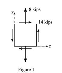
Refer to Figure 1.
Apply the procedure to construct the Mohr’s circle as shown below.
- Find the centre of the circle C located
- Plot the reference points A having coordinates
- Connect the point A with C and from the shaded triangle find the radius R of the circle.
- Sketch the circle once R has been determined.
Construct the Mohr’s circle as shown below.
Calculate the centre of the circle
Substitute
The centre of the circle is
Coordinates of the reference point z.
Substitute
Coordinates of the reference point x.
Substitute
Calculate the radius (R) of the circle as shown below.
Substitute
Sketch the Mohr’s circle as shown in Figure 2.
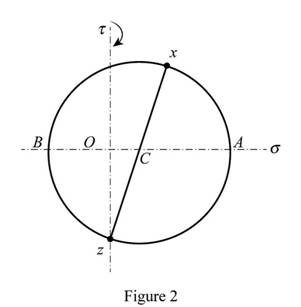
Refer to Figure 2.
Calculate the principal stresses
Substitute
Also the principal stress
Apply maximum distortion energy criterion as shown below.
Substitute
Hence, the factor of safety associated with the yield strength
(b)
The factor of safety associated with the yield strength
(b)
Answer to Problem 39P
The factor of safety associated with the yield strength
Explanation of Solution
Given information:
The stress component along x direction is
The stress component along z direction is
The shear stress component is
The yield stress is
The principal stress is
Calculation:
Refer to part (a).
The principal stresses
Apply maximum distortion energy criterion as shown below.
Substitute
Therefore, the factor of safety associated with the yield strength
Want to see more full solutions like this?
Chapter 11 Solutions
Mechanics of Materials, 7th Edition


- The length of the 332332 -in.-diameter steel wire CD has been adjusted so that with no load applied, a gap of 116116 in. exists between the end B of the rigid beam ACB and contact point E. Knowing that E = 29 × 106 psi, determine where a 57-lb (w) block should be placed on the beam in order to cause contact between B and E. For contact, x < in.arrow_forwardWhat is the Weibull modulus of this material? Would you advise the use of a similar material with a Weibull Modulus of 16.3 and a mean failure stress of 485 MPa, if you anticipate that the peak stress on the material could be 430 MPa? a. 15.7 b. Yes c. 18.6 d. 13.4 e. No f. 17.1arrow_forwardTwo links BF are made of steel with a 450-MPa ultimate normal stress and has a 6x12–mm uniform rectangular cross section. Links BF are connected to members ABD and CDEF by 8-mm diameter pins; ABD and CDEF are connected together by a 10-mm diameter pin; CDEF is connected to the support by a 10-mm diameter pin; all of the pins are made of steel with a 170 MPa ultimate shearing stress. Knowing that a factor of safety of 3 is desired, determine the largest load P that may be appliedarrow_forward
- The driveshaft of an automobile is being designed to transmit 238 hp at 3790 rpm. Determine the minimum diameter d required for a solid steel shaft if the allowable shear stress in the shaft is not to exceed 5700 psi.arrow_forwardThe 2500 N light fixture used in sports gymnasiums is supported by three rods interconnected by an A-ring. Determine the smallest diameters of rods AB, AC and AD, knowing that the limiting voltage of AB is 480Mpa and of AC and AD is 140Mpa. Consider an overall safety factor of 3.3 and θ= 30°.arrow_forwardA flange coupling having 180 mm bolt circle and 19 mm thick uses 12 bolts, 16 mm diameter to connect two shafts. It is used to transmit 80 Hp at 180 rpm. Determine the factor of safety in bearing if yield point in compression is 65 ksi.arrow_forward
- Would you kindly answer this question. If the shaft must have one uniform diameter, determine the required minimum diameter of the shaft if the normal yield stress in the composite shaft must not exceed 450 MPa with a factor of safety equal to 1.8.arrow_forwardThe pipe assembly shown is subjected to a force F = 7 kN and P = 14 kN. It is made of steel with Sy = 250 MPa. Determine the safety factor at point H using the maximum shear stress theory. Select one: a. NH = 6.427 b. NH = 3.570 c. NH = 5.355 d. NH = 4.590arrow_forwardmaterials mechanics A bar of circular cross section is made of an isotropic, linearly elastic material. The material has an elastic limit of 360 MPa. The bar is subjected to two equal and opposite bending moments M2=12 kNm and two equal and opposite torsional moments M1=16 kNm. Determine the minimum diameter of the bar for a safe design using the following factor of safety: F.S=3.arrow_forward
- A large water tank that has a capacity to carry 20,000 liters is to be supported by four cylindrical posts. These four support posts are made of plain carbon (1045) steels with the yield and tensile strengths of 310 MPa and 565 MPa, respectively. Determine the minimum required diameter of the post assuming a factor of safety of 5.arrow_forwardThe pipe assembly shown is subjected to a force F = 400 N. The pipe has an inner diameter of 20 mm and an outer diameter of 30 mm. It is made of steel with Sy = 250 MPa. Determine the safety factor at point A using the maximum shear stress theory. Select one: a. NA = 1.843 b. NA = 3.224 c. NA = 2.580 d. NA = 4.299arrow_forwardDetermine the diameter of a red brass C83400 bar that is 8 ft long if it is to be used to absorb 800 ft # lb of energy in tension from an impact loading. No yielding occurs.arrow_forward
 Elements Of ElectromagneticsMechanical EngineeringISBN:9780190698614Author:Sadiku, Matthew N. O.Publisher:Oxford University Press
 Mechanics of Materials (10th Edition)Mechanical EngineeringISBN:9780134319650Author:Russell C. HibbelerPublisher:PEARSON
 Thermodynamics: An Engineering ApproachMechanical EngineeringISBN:9781259822674Author:Yunus A. Cengel Dr., Michael A. BolesPublisher:McGraw-Hill Education
 Control Systems EngineeringMechanical EngineeringISBN:9781118170519Author:Norman S. NisePublisher:WILEY
 Mechanics of Materials (MindTap Course List)Mechanical EngineeringISBN:9781337093347Author:Barry J. Goodno, James M. GerePublisher:Cengage Learning
 Engineering Mechanics: StaticsMechanical EngineeringISBN:9781118807330Author:James L. Meriam, L. G. Kraige, J. N. BoltonPublisher:WILEY