
Concept explainers
Videos
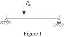
A block of weight W is dropped from a height h onto the horizontal beam AB and hits point D. (a) Denoting by ym the exact value of the maximum deflection at D and by y’m the value obtained by neglecting the effect of this deflection on the change in potential energy of the block, show that the absolute value of the relative error is (y’m — ym)/ym, never exceeding y’m /2h. (b) Check the result obtained in part a by solving part a of Prob. 11.52 without taking ym into account when determining the change in potential energy of the load, and comparing the answer obtained in this way with the exact answer to that problem.
11.52 The 2-kg block D is dropped from the position shown onto the end of a 16-mm-diameter rod. Knowing that E = 200 GPa, determine (a) the maximum deflection of end A, (b) the maximum bending moment in the rod, (c) the maximum normal stress in the rod.
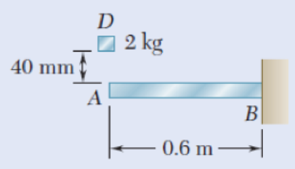
Fig. P11.52
(a)
The absolute value of the relative error
Answer to Problem 57P
The absolute value of the relative error
Explanation of Solution
Calculation:
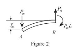
Sketch the loading diagram as shown in Figure 1.
Refer to Figure 1.
Apply the spring constant k for the load applied at point D.
The load
Calculate the maximum strain energy
Substitute
Calculate the work of the block exactly as shown below.
Calculate the work of the block approximately as shown below.
Equating work and strain energy as shown below.
Equating work and strain energy exactly as shown below
Substitute
Equating work and strain energy exactly as shown below
Substitute
Here,
Subtracting Equation (3) from Equation (2) as shown below.
Here,
Substitute
Hence, the absolute value of the relative error
(b)
The relative error of the block.
Answer to Problem 57P
The relative error of the block is
Explanation of Solution
Given information:
The mass of the block is
The modulus of elasticity is
The diameter of the rod is
The length of the beam is
The dropping height is
Calculation:
Refer to part (a).
The relative error is
Consider the acceleration due to gravity as
Calculate the weight of the block as shown below.
Substitute
Calculate the moment of inertia
Substitute
Calculate the moment of inertia
Substitute
Calculate the centroid (c) of the rod as shown below.
Substitute
Sketch the deformation diagram as shown in Figure 2.
Refer to Figure 2.
Refer to Appendix D “Beam Deflections and Slope” in the text book,
Calculate the maximum deflection
Substitute
Calculate the maximum strain energy
Substitute
Calculate the work of the block as shown below.
Substitute
Calculate the maximum deflection
Substitute
Calculate the spring constant
Substitute
Calculate the approximate value of
Substitute
Calculate the relative error as shown below.
Substitute
To check:
Therefore, the relative error is
Want to see more full solutions like this?
Chapter 11 Solutions
Mechanics of Materials, 7th Edition


- A 1.62-oz golf ball is hit with a golf club and leaves it with a velocity of 100 mi/h. We assume that for 0 ≤ t≤t0 , where t0 is the duration of the impact, the magnitude F of the force exerted on the ball can be expressed as F=Fmsin (πt/t0). Knowing that t0 = 0.5 ms, determine the maximum value Fm of the force exerted on the ball.arrow_forward13.61 A bumper composed of three springs is to stop a 40Mg boxcar which is traveling at 1.2m/s as shown. One of the springs is 88mm shorter than the other two. The modulus of the shorter spring is 1.5MN/m while the modulus of the longer two springs is 1MN/m. Determine the maximum deflection of the bumper.arrow_forwardFrom mechanics of materials, it is known that for a simply supported beam of uniform cross section, a static load P applied at the center will cause a deflection of δA=PL3/48 EI, where L is the length of the beam, E is the modulus of elasticity, and I is the moment of inertia of the cross-sectional area of the beam. Knowing that L = 15 ft, E = 30 × 106 psi, and I = 2 × 10 3ft4, determine (a) the equivalent spring constant of the beam, (b) the frequency of vibration of a 1500-lb block attached to the center of the beam. Neglect the mass of the beam and assume that the load remains in contact with the beam.arrow_forward
- A thin circular rod is supported in a vertical plane by a bracket at A. Attached to the bracket and loosely wound around the rod is a spring of constant k= 3 lb/ft and undeformed length equal to the arc of circle AB. An 8-oz collar C , not attached to the spring, can slide without friction along the rod. Knowing that the collar is released from rest at an angle 0 with the vertical, determine (a) the smallest value of 0 for which the collar will pass through D and reach point A, (b) the velocity of the collar as it reaches point A.arrow_forwardNonlinear springs are classified as hard or soft, depending upon the curvature of their force-deflection curve (see figure). If a delicate instrument having a mass of 5 kg is placed on a spring of length I so that its base is just touching the undeformed spring and then inadvertently released from that position, determine the maximum deflection xm of the spring and the maximum force fm exerted by the spring, assuming (a) a linear spring of constant k = 3 kN/m, (b) a hard, nonlinear spring, for which F = (3 kN/m)(x+ 160x3).arrow_forwardNEED WITHIN 1HR THANKS 4.A 1.3-lb sphere A is dropped from a height of 1.8 ft onto 2.6-lb plate B, which is supported by a nested set of springs and is initially at rest. Knowing that the set of springs is equivalent to a single spring of constant k = 5 lb/in., determine the value of the coefficient of restitution between the sphere and the plate for which the height h reached by the sphere after rebound is maximum, the corresponding value of h, and the corresponding value of the maximum deflection of the plate.arrow_forward
- Q.1) A 50 kg block is dropped from a height of 2 m onto the the 20 kg pan of a spring scale.Assuming the impact to be perfectly plastic, determine the maximum deflection of the pan.The constant of the spring is k = 20 kN/m.Q.2) Answer the following questions:a) Why does any person lean towards right while carrying a bag in her left hand?b) Give the physical significance of moment of inertia.c) Two satellites of equal masses, which can be considered as particles areorbiting the earth at different heights? Will their moments of inertia be same ordifferent?Q.3) A 5-kg model rocket is launched vertically and reaches an altitude of 100 m with a speedof 40 m/s at the end of powered flight, time t=5 s. As the rocket approaches its maximumaltitude it explodes into two parts of masses mA=1.7 kg and mB=3.3 kg. Part A is observed tostrike the ground 50 m west of the launch point at t=6 s. Determine the position of part B atthat time.arrow_forwardThe ABC bar has a mass of 2.4 kg and is connected to a support on B. An 800 g D sphere reaches the end A of the bar with a vertical velocity v1 of 3 m / s. Knowing that L = 750 mm and that the coefficient of refund between the sphere and the ABC bar is equal to 0.5, determine immediately after the shock, the angular velocity of the ABC bar and the velocity of the sphere.arrow_forwardSolve Prob. 13.68 assuming the kinetic coefficient of friction between the package and the incline is 0.2.Reference to Problem 13.68:A spring is used to stop a 50-kg package that is moving down a 20° incline. The spring has a constant k = 30 kN/m and is held by cables so that it is initially compressed 50 mm. Knowing that the velocity of the package is 2 m/s when it is 8 m from the spring and neglecting friction, determine the maximum additional deformation of the spring in bringing the package to rest.arrow_forward
- People with mobility impairments can gain great health and social benefits from participating in different recreational activities. You are tasked with designing an adaptive spring-powered shuffleboard attachment that can be utilized by people who use wheelchairs. Knowing that the coefficient of kinetic friction between the 15 ounce puck A and the wooden surface is 0.3, the maximum spring displacement you desire is 6 inches, and that you want the puck to travel at least 30 ft/s, determine (a) the spring constant k, (b) how far the athlete should pull back the spring to make the puck come to rest after 34 ft.arrow_forwardA 30-g bullet is fired with a horizontal velocity of 450 m/s and becomes embedded in block B , which has a mass of 3 kg. After the impact, block B slides on 30-kg carrier C until it impacts the end of the carrier. Knowing the impact between B and C is perfectly plastic and the coefficient of kinetic friction between B and C is 0.2, determine (a) the velocity of the bullet and B after the first impact, (b) the final velocity of the carrier.arrow_forwardFrom mechanics of materials it is known that when a static load P is applied at the end B of a uniform metal rod fixed at end A, the length of the rod will increase by an amount δ=PL/AE, where L is the length of the undeformed rod, A is its cross- sectional area, and E is the modulus of elasticity of the metal. Knowing that L = 450 mm and E = 200 GPa and that the diameter of the rod is 8 mm, and neglecting the mass of the rod, determine (a) the equivalent spring constant of the rod, (b ) the frequency of the vertical vibrations of a block of mass m = 8 kg attached to end B of the same rod.arrow_forward
 Elements Of ElectromagneticsMechanical EngineeringISBN:9780190698614Author:Sadiku, Matthew N. O.Publisher:Oxford University Press
 Mechanics of Materials (10th Edition)Mechanical EngineeringISBN:9780134319650Author:Russell C. HibbelerPublisher:PEARSON
 Thermodynamics: An Engineering ApproachMechanical EngineeringISBN:9781259822674Author:Yunus A. Cengel Dr., Michael A. BolesPublisher:McGraw-Hill Education
 Control Systems EngineeringMechanical EngineeringISBN:9781118170519Author:Norman S. NisePublisher:WILEY
 Mechanics of Materials (MindTap Course List)Mechanical EngineeringISBN:9781337093347Author:Barry J. Goodno, James M. GerePublisher:Cengage Learning
 Engineering Mechanics: StaticsMechanical EngineeringISBN:9781118807330Author:James L. Meriam, L. G. Kraige, J. N. BoltonPublisher:WILEY