Mechanics of Materials
9th Edition
ISBN: 9780133409321
Author: HIBBELER, R. C.
Publisher: Pearson College Div
expand_more
expand_more
format_list_bulleted
Concept explainers
Videos
Textbook Question
Chapter 1.2, Problem 1.1PP
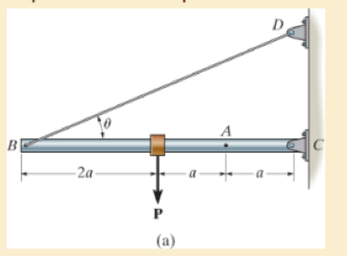
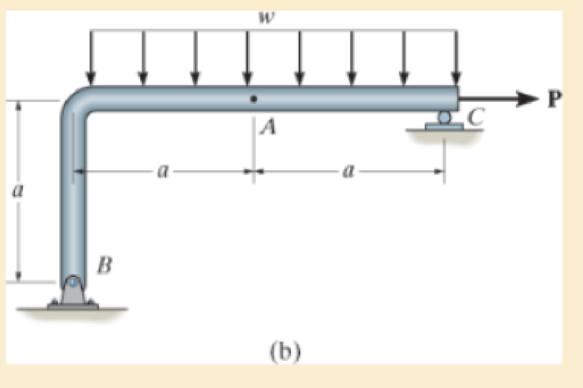
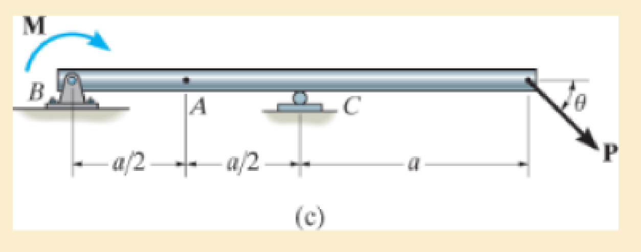
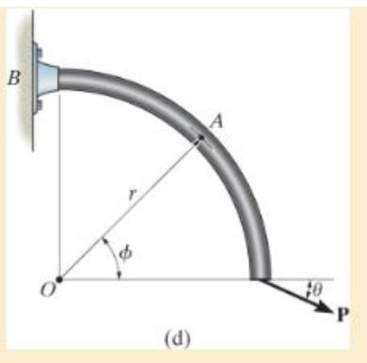
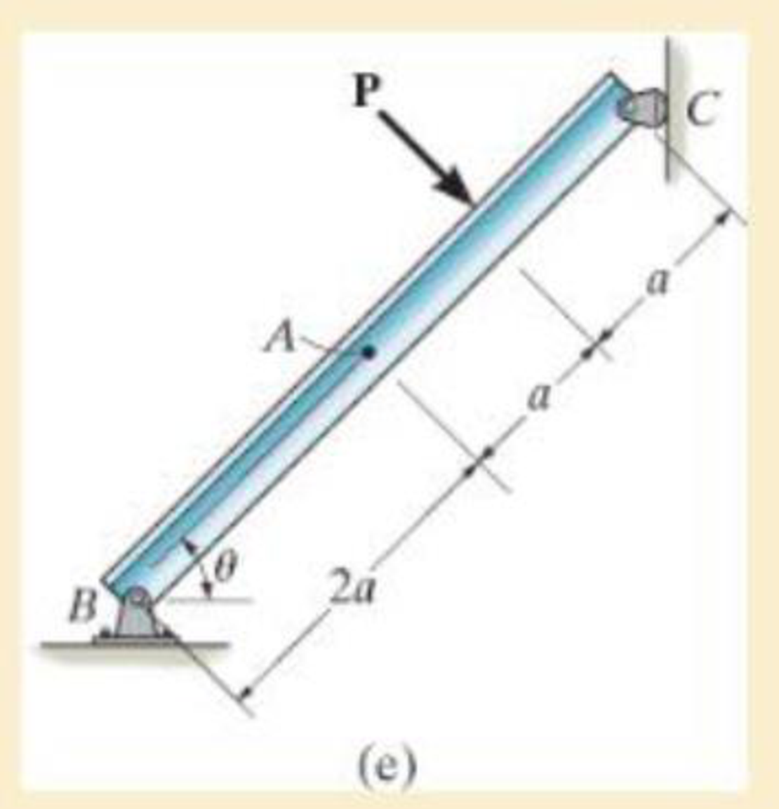
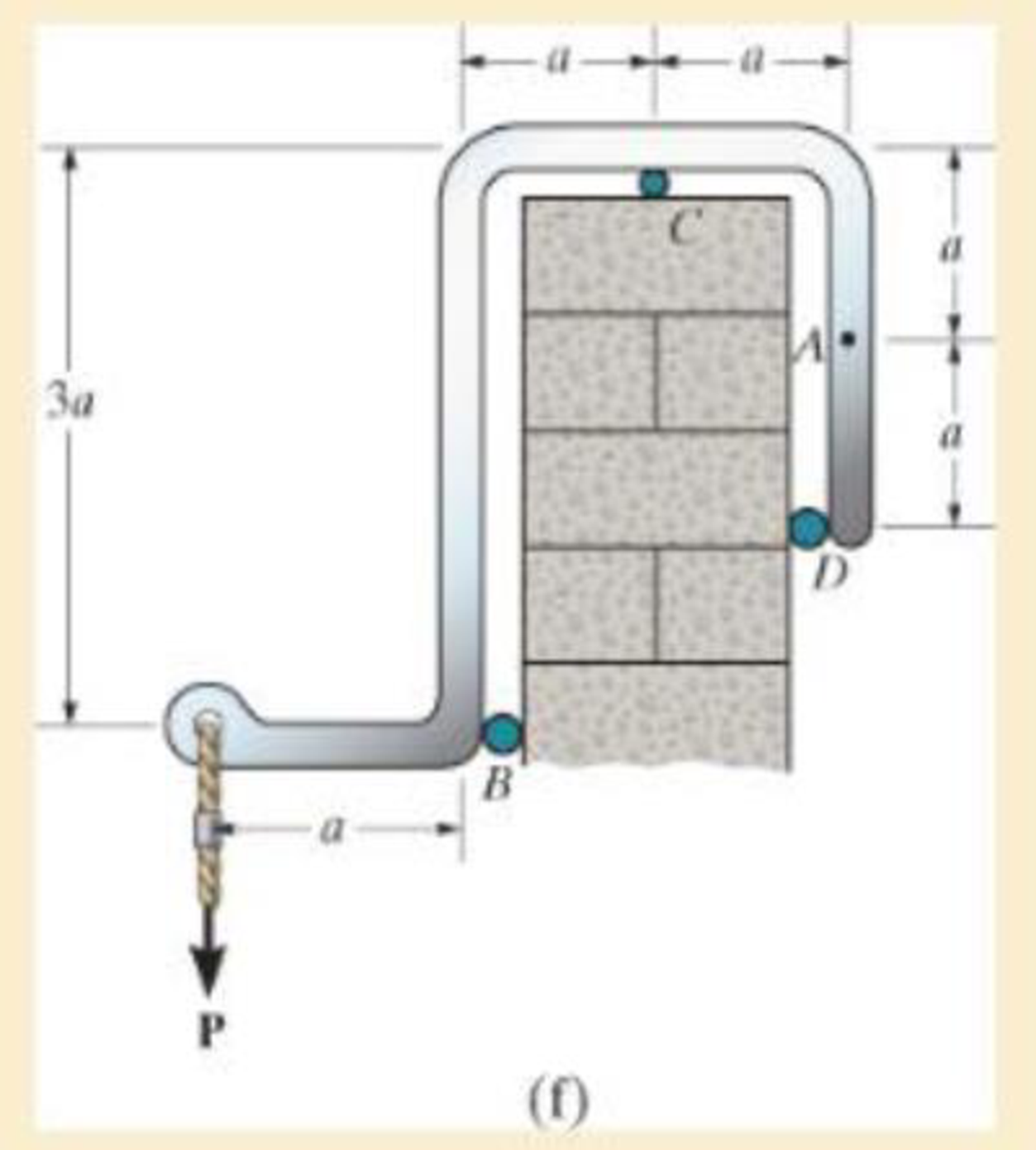
In each case, explain how to find the resultant internal loading acting on the cross section at point A. Draw all necessary free-body diagrams, and indicate the relevant equations of equilibrium. Do not calculate values. The lettered dimensions, angles, and loads are assumed to be known.
Expert Solution & Answer

Trending nowThis is a popular solution!

Students have asked these similar questions
How is this the correct answer?
The beam is subjected to the distributed load and the couple shown. If M is slowly increased starting from zero, at what value M0 will contact at B change from the lower surface to the upper surface?
Please show the complete solution and draw the free body diagram correctly
The pin is used to connect the three links together. Due to wear, the load is distributed over the top and bottom of the pin as shown on the free-body diagram. If the diameter of the pin is 0.40 in., determine the maximum bending stress on the cross-sectional area at the center section a–a. For the solution it is first necessary to determine the load intensities w1 and w2.
Chapter 1 Solutions
Mechanics of Materials
Ch. 1.2 - In each case, explain how to find the resultant...Ch. 1.2 - Determine the resultant internal normal force,...Ch. 1.2 - Determine the resultant internal normal force,...Ch. 1.2 - Determine the resultant internal normal force,...Ch. 1.2 - Determine the resultant internal normal force,...Ch. 1.2 - Determine the resultant internal normal force,...Ch. 1.2 - Determine the resultant internal normal force,...Ch. 1.2 - The shaft is supported by a smooth thrust bearing...Ch. 1.2 - Determine the resultant internal normal and shear...Ch. 1.2 - 1-3. The beam AB is fixed to the wall and has a...
Ch. 1.2 - The shaft is supported by a smooth thrust bearing...Ch. 1.2 - 1-5. Determine the resultant internal loadings in...Ch. 1.2 - 1-6. Determine the normal force, shear force, and...Ch. 1.2 - 1-7. The cable will fail when subjected to a...Ch. 1.2 - *1-8. Determine the resultant internal loadings on...Ch. 1.2 - 1-9. Determine the resultant internal loadings on...Ch. 1.2 - The boom DF of the jib crane and the column DE...Ch. 1.2 - 1-11. The forearm and biceps support the 2-kg load...Ch. 1.2 - *1-12. The serving tray T used on an airplane is...Ch. 1.2 - The blade of the hacksaw is subjected to a...Ch. 1.2 - The blade of the hacksaw is subjected to a...Ch. 1.2 - 1-15. A 150-lb bucket is suspended from a cable on...Ch. 1.2 - *1-16. A 150-lb bucket is suspended from a cable...Ch. 1.2 - 1-17. Determine resultant internal loadings acting...Ch. 1.2 - Prob. 1.18PCh. 1.2 - Prob. 1.19PCh. 1.2 - Prob. 1.20PCh. 1.2 - Prob. 1.21PCh. 1.2 - The metal stud punch is subjected to a force of...Ch. 1.2 - Determine the resultant internal loadings acting...Ch. 1.2 - Prob. 1.24PCh. 1.2 - 1-25. Determine the resultant internal loading...Ch. 1.2 - 1-26. The shaft is supported at its ends by two...Ch. 1.2 - 1-27. The pipe assembly is subjected to a force of...Ch. 1.2 - If the drill bit jams when the brace is subjected...Ch. 1.2 - 1-29. The curved rod AD of radius r has a weight...Ch. 1.2 - A differential element taken from a curved bar is...Ch. 1.5 - In each case, determine the largest internal shear...Ch. 1.5 - Determine the largest internal normal force in the...Ch. 1.5 - Determine the internal normal force at section A...Ch. 1.5 - Prob. 1.5PPCh. 1.5 - The single-V butt joint transmits the force of 5...Ch. 1.5 - The uniform beam is supported by two rods AB and...Ch. 1.5 - Determine the average normal stress on the cross...Ch. 1.5 - Determine the average normal stress on the cross...Ch. 1.5 - If the 600-kN force acts through the centroid of...Ch. 1.5 - Determine the average normal stress at points A,...Ch. 1.5 - Determine the average normal stress in rod AB if...Ch. 1.5 - The supporting wheel on a scaffold is held in...Ch. 1.5 - Prob. 1.32PCh. 1.5 - The bar has a cross-sectional area A and is...Ch. 1.5 - 1-34. The built-up shaft consists of a pipe AB and...Ch. 1.5 - Prob. 1.35PCh. 1.5 - Prob. 1.36PCh. 1.5 - The plate has a width of 0.5 m. If the stress...Ch. 1.5 - The two members used in the construction of an...Ch. 1.5 - Prob. 1.39PCh. 1.5 - Determine the average normal stress in each of the...Ch. 1.5 - If the average normal stress in each of the...Ch. 1.5 - Determine the maximum average shear stress in pin...Ch. 1.5 - 1-43. The 150-kg bucket is suspended from end E of...Ch. 1.5 - *1-44. The 150-kg bucket is suspended from end E...Ch. 1.5 - Prob. 1.45PCh. 1.5 - 1-46. The 20-kg chandelier is suspended from the...Ch. 1.5 - Prob. 1.47PCh. 1.5 - If P = 15 kN, determine the average shear stress...Ch. 1.5 - 1-49. The joint is subjected to the axial member...Ch. 1.5 - Prob. 1.50PCh. 1.5 - Prob. 1.51PCh. 1.5 - Prob. 1.52PCh. 1.5 - Prob. 1.53PCh. 1.5 - Prob. 1.54PCh. 1.5 - The 2-Mg concrete pipe has a center of mass at...Ch. 1.5 - The 2-Mg concrete pipe has a center of mass at...Ch. 1.5 - Prob. 1.57PCh. 1.5 - Prob. 1.58PCh. 1.5 - 1-59. The jib crane is pinned at A and supports a...Ch. 1.5 - *1-60. If the shaft is subjected to an axial force...Ch. 1.5 - Prob. 1.61PCh. 1.5 - Prob. 1.62PCh. 1.5 - Prob. 1.63PCh. 1.5 - *1-64. A vertical force of P = 1500 N is applied...Ch. 1.5 - Prob. 1.65PCh. 1.5 - Determine the largest load P that can be applied...Ch. 1.5 - Prob. 1.67PCh. 1.5 - Prob. 1.68PCh. 1.7 - Rods AC and BC are used to suspend the 200-kg...Ch. 1.7 - If it is subjected to double shear, determine the...Ch. 1.7 - Determine the maximum average shear stress...Ch. 1.7 - If each of the three nails has a diameter of 4 mm...Ch. 1.7 - The strut is glued to the horizontal member at...Ch. 1.7 - Determine the maximum average shear stress...Ch. 1.7 - If the eyebolt is made of a material having a...Ch. 1.7 - If the bar assembly is made of a material having a...Ch. 1.7 - Determine the maximum force P that can be applied...Ch. 1.7 - The pin is made of a material having a failure...Ch. 1.7 - If the bolt head and the supporting bracket are...Ch. 1.7 - Six nails are used to hold the hanger at A against...Ch. 1.7 - If A and B are both made of wood and are 38 in....Ch. 1.7 - Prob. 1.70PCh. 1.7 - Prob. 1.71PCh. 1.7 - Prob. 1.72PCh. 1.7 - The steel swivel bushing in the elevator control...Ch. 1.7 - 1-74. Member B is subjected to a compressive force...Ch. 1.7 - Prob. 1.75PCh. 1.7 - Prob. 1.76PCh. 1.7 - The tension member is fastened together using two...Ch. 1.7 - 1-78. The 50-kg flowerpot is suspended from wires...Ch. 1.7 - 1-79. The 50-kg flowerpot is suspended from wires...Ch. 1.7 - *1–80. The thrust bearing consists of a circular...Ch. 1.7 - 1-81. The steel pipe is supported on the circular...Ch. 1.7 - The steel pipe is supported on the circular base...Ch. 1.7 - 1-83. The 60 mm × 60 mm oak post is supported on...Ch. 1.7 - *1-84. The frame is subjected to the load of 4 kN...Ch. 1.7 - Prob. 1.85PCh. 1.7 - The two aluminum rods support the vertical force...Ch. 1.7 - The two aluminum rods AB and AC have diameters of...Ch. 1.7 - The compound wooden beam is connected together by...Ch. 1.7 - Determine the required minimum thickness t of...Ch. 1.7 - Determine the maximum allowable load P that can be...Ch. 1.7 - Prob. 1.91PCh. 1.7 - *1-92. If the allowable hearing stress for the...Ch. 1.7 - The rods AB and CD are made of steel. Determine...Ch. 1.7 - The aluminum bracket A is used to support the...Ch. 1.7 - Prob. 1.95PCh. 1.7 - *1-96. The pin support A and roller support B of...Ch. 1 - The beam AB is pin supported at A and supported by...Ch. 1 - The long bolt passes through the 30-mm-thick...Ch. 1 - Determine the required thickness of member BC to...Ch. 1 - The circular punch B exerts a force of 2 kN on the...Ch. 1 - Determine the average punching shear stress the...Ch. 1 - The 150 mm by 150 mm block of aluminum supports a...Ch. 1 - The yoke-and-rod connection is subjected to a...Ch. 1 - The cable has a specific weight (weight/volume)...
Additional Engineering Textbook Solutions
Find more solutions based on key concepts
4.12 Calculate the force in each cable for the suspended weight shown.
Applied Statics and Strength of Materials (6th Edition)
The moment of force about point O.
Engineering Mechanics: Statics & Dynamics (14th Edition)
In each case, determine the moment of the force about point O. Prob. P3-1
Statics and Mechanics of Materials (5th Edition)
14. When one tries to stop a car, both the reaction time of the driver and the braking time must be considered....
Thinking Like an Engineer: An Active Learning Approach (4th Edition)
Determine the magnitude of the horizontal force F = Fi acting on the handle of the wrench so that this force pr...
INTERNATIONAL EDITION---Engineering Mechanics: Statics, 14th edition (SI unit)
ICA 7-1
Express the following values using scientific notation, engineering notation, and using an appropriate ...
Thinking Like an Engineer: An Active Learning Approach (3rd Edition)
Knowledge Booster


Learn more about
Need a deep-dive on the concept behind this application? Look no further. Learn more about this topic, mechanical-engineering and related others by exploring similar questions and additional content below.Similar questions
- The bearings at A and D exert only y and z components of force on the shaft as shown in Fig 7. Determine the smallest diameter of the shaft using maximum shear stress hypothesis theory if the allowable stress is 100 MPa.arrow_forwardDetermine the load P if the end C is displaced 0.075 in. downward.arrow_forwardDraw the Free Body Diagram and solve the problemarrow_forward
- In each case, determine the internal normal force between lettered points on the bar. Draw all necessary free-body diagrams.arrow_forwardDetermine the maximum deformation of the bar when subjected to the load systemarrow_forwardThe axle of the freight train is subjected to loadings as shown below. The diameter of the axle is 137.5 mm. If it is supported by two journal bearings at C and D, determine the maximum bending Stress. Include a FBD, SFD and BMD using either the section or graphical method. Draw a cross-section of the shaft and indicate the points of maximum tension and compression.arrow_forward
- The W24 * 104 A-36 steel beam is used to support the uniform distributed load and a concentrated force which is applied at its end. If the force acts at an angle with the vertical as shown, determine the horizontal and vertical displacement at A.arrow_forwardDetermine the shape factor for the member having the tubular cross section.arrow_forwardThe stress–strain diagram for a titanium alloy can be approximated by the two straight lines. If a strut made of this material is subjected to bending, determine the moment resisted by the strut if the maximum stress reaches a value of (a) sA and (b) sB.arrow_forward
- The bar is made of an aluminum alloy having a stress–strain diagram that can be approximated by the straight line segments shown. Assuming that this diagram is the same for both tension and compression, determine the moment the bar will support if the maximum strain at the top and bottom fibers of the beam is Pmax = 0.05.arrow_forwardThe eye hook has the dimensions shown. If it supports a cable loading of 800 lb, determine the maximum normal stress at section a–a and sketch the stress distribution acting over the cross section. Use the curved-beam formula to calculate the bending stress.arrow_forward1–1. The shaft is supported by a smooth thrust bearing at B and a journal bearing at C. Determine the resultant internal loadings acting on the cross section at E. Problem 1–1arrow_forward
arrow_back_ios
SEE MORE QUESTIONS
arrow_forward_ios
Recommended textbooks for you
 Elements Of ElectromagneticsMechanical EngineeringISBN:9780190698614Author:Sadiku, Matthew N. O.Publisher:Oxford University Press
 Mechanics of Materials (10th Edition)Mechanical EngineeringISBN:9780134319650Author:Russell C. HibbelerPublisher:PEARSON
 Thermodynamics: An Engineering ApproachMechanical EngineeringISBN:9781259822674Author:Yunus A. Cengel Dr., Michael A. BolesPublisher:McGraw-Hill Education
 Control Systems EngineeringMechanical EngineeringISBN:9781118170519Author:Norman S. NisePublisher:WILEY
 Mechanics of Materials (MindTap Course List)Mechanical EngineeringISBN:9781337093347Author:Barry J. Goodno, James M. GerePublisher:Cengage Learning
 Engineering Mechanics: StaticsMechanical EngineeringISBN:9781118807330Author:James L. Meriam, L. G. Kraige, J. N. BoltonPublisher:WILEY
Elements Of Electromagnetics
Mechanical Engineering
ISBN:9780190698614
Author:Sadiku, Matthew N. O.
Publisher:Oxford University Press
Mechanics of Materials (10th Edition)
Mechanical Engineering
ISBN:9780134319650
Author:Russell C. Hibbeler
Publisher:PEARSON
Thermodynamics: An Engineering Approach
Mechanical Engineering
ISBN:9781259822674
Author:Yunus A. Cengel Dr., Michael A. Boles
Publisher:McGraw-Hill Education
Control Systems Engineering
Mechanical Engineering
ISBN:9781118170519
Author:Norman S. Nise
Publisher:WILEY
Mechanics of Materials (MindTap Course List)
Mechanical Engineering
ISBN:9781337093347
Author:Barry J. Goodno, James M. Gere
Publisher:Cengage Learning
Engineering Mechanics: Statics
Mechanical Engineering
ISBN:9781118807330
Author:James L. Meriam, L. G. Kraige, J. N. Bolton
Publisher:WILEY
EVERYTHING on Axial Loading Normal Stress in 10 MINUTES - Mechanics of Materials; Author: Less Boring Lectures;https://www.youtube.com/watch?v=jQ-fNqZWrNg;License: Standard YouTube License, CC-BY