Mechanics of Materials
9th Edition
ISBN: 9780133254426
Author: Russell C. Hibbeler
Publisher: Prentice Hall
bartleby

Videos

Textbook Question
Book Icon
Chapter 12, Problem 12.133RP

Determine the equation of the elastic curve. Use discontinuity functions EI is constant.

Chapter 12, Problem 12.133RP, Determine the equation of the elastic curve. Use discontinuity functions EI is constant.

Expert Solution & Answer
Check Mark
To determine
The Equation of the elastic curve.

Answer to Problem 12.133RP

The Equation of the elastic curve is,

v=1EI[30x3+46.25(x12)311.7(x24)3+38703.24x412,598.88]lbin3_.

Explanation of Solution

Given information:

The length of the beam is 60 in..

EI is constant.

Calculation:

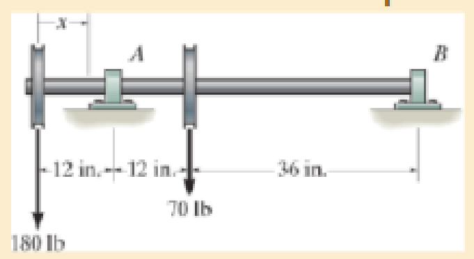
Sketch the Free Body Diagram of the beam as shown in Figure 1.
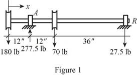
Mechanics of Materials, Chapter 12, Problem 12.133RP

Refer to Figure 1.

Find the support reaction as shown below.

Apply the Equations of Equilibrium as shown below.

Take moment about A is Equal to zero.

MA=0By×4870×12+180×12=048By+1,320=0By=27.5lb

Summation of forces along vertical direction is Equal to zero.

Fy=0Ay27.518070=0Ay277.5=0Ay=277.5lb

Consider the x distance from left support.

Take moment about the section as shown below.

M(x)=180(x0)(277.5)×(x12)70×(x24)=180x+277.5(x12)70(x24)

Apply the slope and elastic curve as shown below.

EId2vdx2=M(x) (1)

Here, EI is the flexural rigidity, d2vdx2 is the second derivatives of the function v, and M(x) is the moment at the section x.

Substitute 180x+277.5(x12)70(x24) for M(x) in Equation (1).

EId2vdx2=180x+277.5(x12)70(x24)

Integrate both sides of the Equation.

EId2vdx2=(180x+277.5(x12)70(x24))EIdvdx=180x22+277.5(x12)2270(x24)22+C1EIdvdx=90x2+138.75(x12)235(x24)2+C1 (2)

Integrate both sides of the Equation (2).

EIdvdx=(90x2+138.75(x12)235(x24)2+C1)EIv=90x33+138.75(x12)3335(x24)33+C1x+C2EIv=30x3+46.25(x12)311.67(x24)3+C1x+C2 (3)

Apply the boundary conditions as shown below.

  1. i. The value of v=0 at x=12in..
  2. ii. The value of v=0 at x=60in..

Apply boundary condition (i) in Equation (3).

Substitute 0 for v and 12 I              n. for x in Equation (3).

EI(0)=30(12)3+46.25(1212)3+C1×12+C212C1+C251,840=0 (4)

Apply boundary condition (ii) in Equation (3).

Substitute 0 for v and 60 in. for x in Equation (3).

EI(0)=30(60)3+46.25(6012)311.67(6024)3+C1(60)+C260C1+C21,909,595.52=0 (5)

Solving Equations (4) and (5) we get,

C1=38703.24C2=412,598.88

Substitute 38703.24 for C1 and 412,598.88 for C2 in Equation (3).

EIv=[30x3+46.25(x12)311.67(x24)3+38703.24x412,598.88]v=1EI[30x3+46.25(x12)311.67(x24)3+38703.24x412,598.88]lbin3

Therefore, the Equation of the elastic curve is,

v=1EI[30x3+46.25(x12)311.67(x24)3+38703.24x412,598.88]lbin3_.

Want to see more full solutions like this?

Subscribe now to access step-by-step solutions to millions of textbook problems written by subject matter experts!
08:17
Students have asked these similar questions
Determine the equation of the elastic curve. Specify the slopes at A and B. EI is constant.
Determine the equations of the elastic curve using the coordinates x1 and x2. EI is constant.
The shaft supports the two pulley loads shown. Determine the equation of the elastic curve. EI is constant.

Chapter 12 Solutions

Mechanics of Materials

Ch. 12.2 - Prob. 12.4PCh. 12.2 - 12-5. Determine the deflection of end C of the...Ch. 12.2 - Prob. 12.6PCh. 12.2 - Prob. 12.7PCh. 12.2 - Determine the equations of the elastic curve using...Ch. 12.2 - Determine the equations of the elastic curve for...Ch. 12.2 - 12-10. Determine the equations of the elastic...Ch. 12.2 - 12-11. Determine the deflection at the center of...Ch. 12.2 - Prob. 12.12PCh. 12.2 - Determine the maximum deflection of the beam and...Ch. 12.2 - The simply supported shaft has a moment of inertia...Ch. 12.2 - 12-15. The two wooden meter sticks are separated...Ch. 12.2 - Prob. 12.16PCh. 12.2 - Prob. 12.17PCh. 12.2 - The bar is supported by a roller constraint at B,...Ch. 12.2 - Determine the deflection at B of the bar in Prob....Ch. 12.2 - Determine the equations of the elastic curve using...Ch. 12.2 - Determine the maximum deflection of the solid...Ch. 12.2 - Determine the elastic curve for the cantilevered...Ch. 12.2 - Determine the equations of the elastic curve using...Ch. 12.2 - Determine the equations of the elastic curve using...Ch. 12.2 - The floor beam of the airplane is subjected to the...Ch. 12.2 - Determine the maximum deflection of the simply...Ch. 12.2 - Prob. 12.27PCh. 12.2 - Determine the slope at end B and the maximum...Ch. 12.2 - Determine the equation of the elastic curve using...Ch. 12.2 - Determine the equations of the elastic curve using...Ch. 12.3 - The shaft is supported at A by a journal bearing...Ch. 12.3 - The shaft supports the two pulley loads shown....Ch. 12.3 - 12-33. Determine the equation of the elastic...Ch. 12.3 - Determine the equation of the elastic curve, the...Ch. 12.3 - The beam is subjected to the load shown. Determine...Ch. 12.3 - Determine the equation of the elastic curve, the...Ch. 12.3 - Determine the equation of the elastic curve and...Ch. 12.3 - 12-38. The beam is subjected to the loads shown....Ch. 12.3 - Determine the maximum deflection of the...Ch. 12.3 - Determine the slope at A and the deflection of end...Ch. 12.3 - Determine the maximum deflection in region AB of...Ch. 12.3 - Prob. 12.42PCh. 12.3 - Prob. 12.43PCh. 12.3 - Prob. 12.44PCh. 12.3 - Prob. 12.45PCh. 12.3 - Prob. 12.46PCh. 12.3 - 12-47. The shaft is made of steel and has a...Ch. 12.3 - Prob. 12.48PCh. 12.3 - Determine the displacement at C and the slope at...Ch. 12.3 - Determine the equations of the slope and elastic...Ch. 12.4 - Determine the slope and deflection of end A of the...Ch. 12.4 - Determine the slope and deflection of end A of the...Ch. 12.4 - Determine the slope and deflection of end A of the...Ch. 12.4 - Determine the slope and deflection at A of the...Ch. 12.4 - Prob. 12.11FPCh. 12.4 - Determine the maximum deflection of the simply...Ch. 12.4 - Determine the slope and deflection at C. El is...Ch. 12.4 - Determine the slope and deflection at C. El is...Ch. 12.4 - Determine the deflection of end B of the...Ch. 12.4 - Prob. 12.54PCh. 12.4 - The composite simply supported steel shaft is...Ch. 12.4 - Prob. 12.56PCh. 12.4 - Prob. 12.57PCh. 12.4 - Determine the deflection at C and the slope of the...Ch. 12.4 - Prob. 12.59PCh. 12.4 - Prob. 12.60PCh. 12.4 - Determine the position a of the roller support B...Ch. 12.4 - Prob. 12.62PCh. 12.4 - Determine the slope and the deflection of end B of...Ch. 12.4 - Prob. 12.64PCh. 12.4 - Determine the slope at A and the displacement at...Ch. 12.4 - Determine the deflection at C and the slopes at...Ch. 12.4 - Determine the maximum deflection within region AB....Ch. 12.4 - Determine the slope at A and the maximum...Ch. 12.4 - Determine the slope at C and the deflection at B....Ch. 12.4 - Determine the slope at A and the maximum...Ch. 12.4 - Prob. 12.71PCh. 12.4 - Prob. 12.72PCh. 12.4 - Prob. 12.73PCh. 12.4 - The rod is constructed from two shafts for which...Ch. 12.4 - Prob. 12.75PCh. 12.4 - Determine the slope at point A and the maximum...Ch. 12.4 - Determine the position a of roller support B in...Ch. 12.4 - Determine the slope at B and deflection at C. El...Ch. 12.4 - Prob. 12.79PCh. 12.4 - Prob. 12.80PCh. 12.4 - Prob. 12.81PCh. 12.4 - Determine the maximum deflection of the beam. El...Ch. 12.5 - The W10 15 cantilevered beam is made of A-36...Ch. 12.5 - The W10 15 cantilevered beam is made of A-36...Ch. 12.5 - 12-85. Determine the slope and deflection at end C...Ch. 12.5 - 12-86. Determine the slope at A and the deflection...Ch. 12.5 - Prob. 12.87PCh. 12.5 - Prob. 12.88PCh. 12.5 - 12-89. The W8 × 24 simply supported beam is made...Ch. 12.5 - 12-90. The simply supported beam carries a uniform...Ch. 12.5 - Prob. 12.91PCh. 12.5 - *12-92. The W10 × 30 cantilevered beam is made of...Ch. 12.5 - The rod is pinned at its end A and attached to a...Ch. 12.5 - Prob. 12.94PCh. 12.5 - The pipe assembly consists of three equal-sized...Ch. 12.5 - *12-96. The framework consists of two A992 steel...Ch. 12.5 - Prob. 12.97PCh. 12.5 - 12-98. Determine the vertical deflection at the...Ch. 12.7 - Determine the reactions at the supports A and B,...Ch. 12.7 - Prob. 12.100PCh. 12.7 - Determine the reactions at the supports A, B, and...Ch. 12.7 - Determine the reactions at the supports A and B,...Ch. 12.7 - Determine the reactions at the supports A and B,...Ch. 12.7 - Prob. 12.104PCh. 12.7 - 12-105. Use discontinuity functions and determine...Ch. 12.7 - Determine the reactions at the support A and B. EI...Ch. 12.7 - 12-107. Determine the reactions at pin support A...Ch. 12.7 - Determine the moment reactions at the supports A...Ch. 12.7 - The beam has a constant E1I1 and is supported by...Ch. 12.7 - The beam is supported by a pin at A, a roller at...Ch. 12.8 - Determine the moment reactions at the supports A...Ch. 12.8 - Prob. 12.112PCh. 12.8 - Determine the vertical reaction at the journal...Ch. 12.8 - Determine the reactions at the supports A and B,...Ch. 12.8 - Prob. 12.115PCh. 12.8 - Determine the vertical reaction at the journal...Ch. 12.9 - Determine the reactions at the fixed support A and...Ch. 12.9 - Determine the reactions at the fixed support A and...Ch. 12.9 - Determine the reactions at the fixed support A and...Ch. 12.9 - Determine the reaction at the roller B. EI is...Ch. 12.9 - Determine the reaction at the roller B. EI is...Ch. 12.9 - Determine the reaction at the roller support B if...Ch. 12.9 - Determine the reactions at the journal bearing...Ch. 12.9 - Prob. 12.118PCh. 12.9 - 12-119. Determine the reactions at the supports A,...Ch. 12.9 - Prob. 12.120PCh. 12.9 - 12-121. Determine the deflection at the end B of...Ch. 12.9 - Determine the reactions at the supports A and B....Ch. 12.9 - Prob. 12.123PCh. 12.9 - Before the uniform distributed load is applied to...Ch. 12.9 - The fixed supported beam AB is strengthened using...Ch. 12.9 - 12-126. Determine the force in the spring. EI is...Ch. 12.9 - The beam is supported by the bolted supports at...Ch. 12.9 - Each of the two members is made from 6061-T6...Ch. 12.9 - The beam is made from a soft linear elastic...Ch. 12.9 - Prob. 12.130PCh. 12.9 - 12–131. The 1-in -diameter A-36 steel shaft is...Ch. 12.9 - Prob. 12.132PCh. 12 - Determine the equation of the elastic curve. Use...Ch. 12 - Draw the bending-moment diagram for the shaft and...Ch. 12 - Determine the moment reactions at the supports A...Ch. 12 - Specify the slope at A and the maximum deflection....Ch. 12 - Determine the maximum deflection between the...Ch. 12 - Determine the slope at B and the deflection at C....Ch. 12 - Determine the reactions, then draw the shear and...Ch. 12 - El is constant.Ch. 12 - Using the method of superposition, determine the...Ch. 12 - The rim on the flywheel has a thickness t, width...

Additional Engineering Textbook Solutions

Find more solutions based on key concepts
The free body diagram of the ring at A. The magnitude of force in each cable.

Engineering Mechanics: Statics & Dynamics (14th Edition)

If a = 6 ft, determine the greatest load P the truss can support. Probs. 6-13/14/15

INTERNATIONAL EDITION---Engineering Mechanics: Statics, 14th edition (SI unit)

What parts are included in the vehicle chassis?

Automotive Technology: Principles, Diagnosis, And Service (6th Edition) (halderman Automotive Series)

Knowledge Booster
Background pattern image
Mechanical Engineering
Learn more about
Need a deep-dive on the concept behind this application? Look no further. Learn more about this topic, mechanical-engineering and related others by exploring similar questions and additional content below.
Similar questions
SEE MORE QUESTIONS
Recommended textbooks for you
Text book image
Elements Of Electromagnetics
Mechanical Engineering
ISBN:9780190698614
Author:Sadiku, Matthew N. O.
Publisher:Oxford University Press
Text book image
Mechanics of Materials (10th Edition)
Mechanical Engineering
ISBN:9780134319650
Author:Russell C. Hibbeler
Publisher:PEARSON
Text book image
Thermodynamics: An Engineering Approach
Mechanical Engineering
ISBN:9781259822674
Author:Yunus A. Cengel Dr., Michael A. Boles
Publisher:McGraw-Hill Education
Text book image
Control Systems Engineering
Mechanical Engineering
ISBN:9781118170519
Author:Norman S. Nise
Publisher:WILEY
Text book image
Mechanics of Materials (MindTap Course List)
Mechanical Engineering
ISBN:9781337093347
Author:Barry J. Goodno, James M. Gere
Publisher:Cengage Learning
Text book image
Engineering Mechanics: Statics
Mechanical Engineering
ISBN:9781118807330
Author:James L. Meriam, L. G. Kraige, J. N. Bolton
Publisher:WILEY
Relationship Between Elastic Constants and Connecting Equations; Author: Engineers Academy;https://www.youtube.com/watch?v=whW5PnM7Pug;License: Standard Youtube License