Microelectronics: Circuit Analysis and Design
4th Edition
ISBN: 9780073380643
Author: Donald A. Neamen
Publisher: McGraw-Hill Companies, The
bartleby

Videos

Question
Book Icon
Chapter 12, Problem 12.9TYU
To determine

To show: The variation in magnitude of the input resistance Rif as the feedback resistance varies.

To explain: The influence of Rif on RF .

Expert Solution & Answer
Check Mark

Answer to Problem 12.9TYU

The influence of RF on Rif is determined by the relation RF(1RC12||RB2)+(Aifgm2(RC2+RLRC2))(1RC||RB2||rπ2)gm1+[(RFRs||RB1||rπ1||RF)(1RC1||RB2)] and the plot for the variation in the input resistance when the feedback resistance is varied between 5kΩ and 50kΩ is shown in Figure 6.

Explanation of Solution

Given:

The given diagram is shown in Figure 1

  Microelectronics: Circuit Analysis and Design, Chapter 12, Problem 12.9TYU , additional homework tip  1

Figure 1

Feedback resistor value is varied between 5kΩ and 50kΩ

Calculation:

Mark the nodes and redraw the circuit.

The given diagram is shown in Figure 2
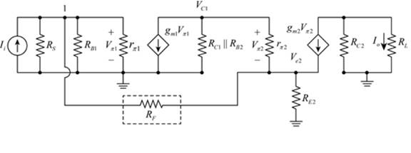
  Microelectronics: Circuit Analysis and Design, Chapter 12, Problem 12.9TYU , additional homework tip  2

Figure 2

Mark the values and draw the PSpice circuit for the above circuit.

The required circuit is shown in Figure 3
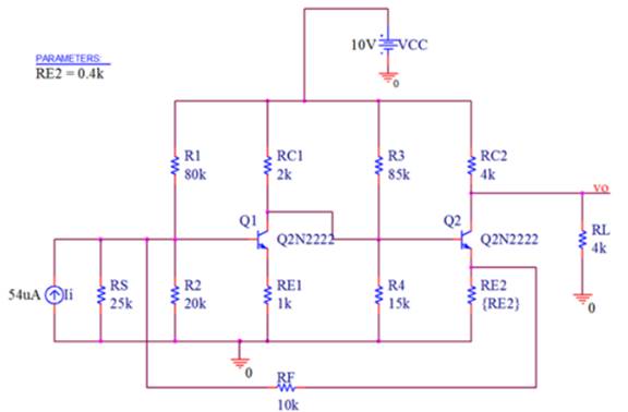
  Microelectronics: Circuit Analysis and Design, Chapter 12, Problem 12.9TYU , additional homework tip  3

Figure 3

The snip for the drop box of the internal parameters of the transistor is shown in Figure 4
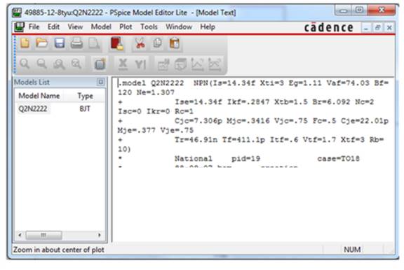
  Microelectronics: Circuit Analysis and Design, Chapter 12, Problem 12.9TYU , additional homework tip  4

Figure 4

The simulation settings to estimate the magnitude of the current gain as the value of
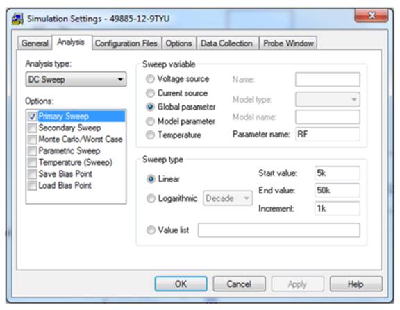
 RF is varied between 5kΩ and 50kΩ is shown in Figure 5

  Microelectronics: Circuit Analysis and Design, Chapter 12, Problem 12.9TYU , additional homework tip  5

Figure 5

Then left click on the trace option then select add trace and type “ABS(V(vi)l(li))” then command in the trace magnitude of the resistance
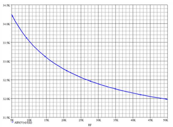
 Rif as the feedback resistance varies between 5kΩ and 50kΩ , the required relation is shown in Figure 6

  Microelectronics: Circuit Analysis and Design, Chapter 12, Problem 12.9TYU , additional homework tip  6

Figure 6

By KCL the expression for the current Ii is given by,

  Ii=Vπ1Rs||RB1||rπ1+Vπ1Ve2RFVe2=Vπ1(RFRs||RB1||rπ1||RF)IiRF

The expression for the node voltage is given by,

  VC1=Vπ2+Ve2

Apply KCL at node VC1 .

  gm1Vπ1+VC1RC1||RB2+Vπ2rπ2=0gm1Vπ1+Vπ2+Ve2RC1||RB2+Vπ2rπ2=0gm1Vπ1+Vπ2(1RC1||RB2||rπ2)+Ve2RC12||RB2=0

Substitute Vπ1(RFRs||RB1||rπ1||RF)IiRF for Ve2 in the above equation.

  gm1Vπ1+Vπ2(1RC1||RB2||rπ2)+1RC12||RB2[Vπ1(RFRs||RB1||rπ1||RF)IiRF]=0Vπ1=IiRF(1RC12||RB2)Vπ2(1RC||RB2||rπ2)gm1+[(RFRs||RB1||rπ1||RF)(1RC1||RB2)] …… (1)

Consider A=RFRs||RB1||rπ1||RF , B=1RE2+1RF , C=1RC1||RB2 and D=1RC1||RB2||rπ2 in the above equation. So the equation is,

  Vπ1=IiRFCVπ2Dgm1+[AC]

The expression for the output current is given by,

  IO=(gm2Vπ2)(RC2RC2+RL)Vπ2=IOgm2(RC2+RLRC2)

Substitute IOgm2(RC2+RLRC2) for Vπ2 in equation (1).

  Vπ1=IiRF(1RC12||RB2)(IOgm2(RC2+RLRC2))(1RC||RB2||rπ2)gm1+[(RFRs||RB1||rπ1||RF)(1RC1||RB2)]

Substitute AifIi for IO in the above equation.

   V π1 = I i R F ( 1 R C12 || R B2 )+( A if I i g m2 ( R C2 + R L R C2 ) )( 1 R C || R B2 || r π2 ) g m1 +[ ( R F R s || R B1 || r π1 || R F )( 1 R C1 || R B2 ) ]

   V π1 I i = R F ( 1 R C12 || R B2 )+( A if g m2 ( R C2 + R L R C2 ) )( 1 R C || R B2 || r π2 ) g m1 +[ ( R F R s || R B1 || r π1 || R F )( 1 R C1 || R B2 ) ]

   R if = R F ( 1 R C12 || R B2 )+( A if g m2 ( R C2 + R L R C2 ) )( 1 R C || R B2 || r π2 ) g m1 +[ ( R F R s || R B1 || r π1 || R F )( 1 R C1 || R B2 ) ]

Conclusion:

Therefore, the influence of RF on Rif is determined by the relation RF(1RC12||RB2)+(Aifgm2(RC2+RLRC2))(1RC||RB2||rπ2)gm1+[(RFRs||RB1||rπ1||RF)(1RC1||RB2)] and the plot for the variation in the input resistance when the feedback resistance is varied between 5kΩ and 50kΩ is shown in Figure 6

Want to see more full solutions like this?

Subscribe now to access step-by-step solutions to millions of textbook problems written by subject matter experts!
Students have asked these similar questions
Discuss the difference between the current series negative feedback amplifier and voltage shunt feedback amplifier in terms of output impedance, input impedance, voltage gain, bandwidth, distortion and noise.
Loop gain analysis in a feedback system applies for __________.  Option (1) small-signal perturbations  Option (2) large-signal perturbations  Option (3) both large and small-signal perturbations
State whether the following statement is true or false. “Dominant pole compensation increases the unity-loop-gain bandwidth of a feedback system.”   Please answer with few line explanation.

Chapter 12 Solutions

Microelectronics: Circuit Analysis and Design

Ch. 12 - Prob. 12.5TYUCh. 12 - Consider the noninverting op-amp circuit shown in...Ch. 12 - Design a feedback voltage amplifier to provide a...Ch. 12 - Prob. 12.6TYUCh. 12 - (a) Assume the transistor in the source-follower...Ch. 12 - Consider the common-base circuit in Figure...Ch. 12 - Design a feedback current amplifier to provide a...Ch. 12 - Prob. 12.8TYUCh. 12 - Prob. 12.9TYUCh. 12 - For the circuit in Figure 12.31, the transistor...Ch. 12 - Design a transconductance feedback amplifier with...Ch. 12 - Prob. 12.10TYUCh. 12 - Consider the circuit in Figure 12.39, with...Ch. 12 - Consider the BJT feedback circuit in Figure...Ch. 12 - Prob. 12.12TYUCh. 12 - Consider the circuit in Figure...Ch. 12 - Prob. 12.16EPCh. 12 - Prob. 12.17EPCh. 12 - Consider the circuit in Figure 12.44(a) with...Ch. 12 - Consider the circuit in Figure 12.16 with the...Ch. 12 - Prob. 12.18EPCh. 12 - Consider the loop gain function T(f)=(3000)(1+jf...Ch. 12 - Consider the loop gain function given in Exercise...Ch. 12 - Prob. 12.16TYUCh. 12 - Prob. 12.17TYUCh. 12 - Prob. 12.20EPCh. 12 - Prob. 12.21EPCh. 12 - Prob. 12.22EPCh. 12 - What are the two general types of feedback and...Ch. 12 - Prob. 2RQCh. 12 - Prob. 3RQCh. 12 - Prob. 4RQCh. 12 - Prob. 5RQCh. 12 - Prob. 6RQCh. 12 - Describe the series and shunt output connections...Ch. 12 - Describe the effect of a series or shunt input...Ch. 12 - Describe the effect of a series or shunt output...Ch. 12 - Consider a noninverting op-amp circuit. Describe...Ch. 12 - Prob. 11RQCh. 12 - What is the Nyquist stability criterion for a...Ch. 12 - Using Bode plots, describe the conditions of...Ch. 12 - Prob. 14RQCh. 12 - Prob. 15RQCh. 12 - Prob. 16RQCh. 12 - Prob. 17RQCh. 12 - (a) A negative-feedback amplifier has a...Ch. 12 - Prob. 12.2PCh. 12 - The ideal feedback transfer function is given by...Ch. 12 - Prob. 12.4PCh. 12 - Consider the feedback system shown in Figure 12.1...Ch. 12 - The open-loop gain of an amplifier is A=5104. If...Ch. 12 - Two feedback configurations are shown in Figures...Ch. 12 - Three voltage amplifiers are in cascade as shown...Ch. 12 - (a) The open-loop low-frequency voltage gain of an...Ch. 12 - (a) Determine the closed-loop bandwidth of a...Ch. 12 - (a) An inverting amplifier uses an op-amp with an...Ch. 12 - The basic amplifier in a feedback configuration...Ch. 12 - Consider the two feedback networks shown in...Ch. 12 - Prob. 12.14PCh. 12 - Two feedback configurations are shown in Figures...Ch. 12 - Prob. 12.16PCh. 12 - The parameters of the ideal series-shunt circuit...Ch. 12 - For the noninverting op-amp circuit in Figure...Ch. 12 - Consider the noninverting op-amp circuit in Figure...Ch. 12 - The circuit parameters of the ideal shunt-series...Ch. 12 - Consider the ideal shunt-series amplifier shown in...Ch. 12 - Consider the op-amp circuit in Figure P12.22. The...Ch. 12 - An op-amp circuit is shown in Figure P12.22. Its...Ch. 12 - Prob. 12.24PCh. 12 - Prob. 12.25PCh. 12 - Consider the circuit in Figure P12.26. The input...Ch. 12 - The circuit shown in Figure P12.26 has the same...Ch. 12 - The circuit parameters of the ideal shunt-shunt...Ch. 12 - Prob. 12.29PCh. 12 - Consider the current-to-voltage converter circuit...Ch. 12 - Prob. 12.31PCh. 12 - Determine the type of feedback configuration that...Ch. 12 - Prob. 12.33PCh. 12 - A compound transconductance amplifier is to be...Ch. 12 - The parameters of the op-amp in the circuit shown...Ch. 12 - Prob. 12.36PCh. 12 - Consider the series-shunt feedback circuit in...Ch. 12 - The circuit shown in Figure P12.38 is an ac...Ch. 12 - Prob. 12.39PCh. 12 - Prob. 12.40PCh. 12 - Prob. 12.41PCh. 12 - Prob. 12.42PCh. 12 - Prob. D12.43PCh. 12 - Prob. D12.44PCh. 12 - An op-amp current gain amplifier is shown in...Ch. 12 - Prob. 12.46PCh. 12 - Prob. 12.47PCh. 12 - Prob. 12.48PCh. 12 - The circuit in Figure P 12.49 has transistor...Ch. 12 - (a) Using the small-signal equivalent circuit in...Ch. 12 - The circuit in Figure P12.51 is an example of a...Ch. 12 - Prob. 12.52PCh. 12 - For the transistors in the circuit in Figure P...Ch. 12 - Consider the transconductance amplifier shown in...Ch. 12 - Consider the transconductance feedback amplifier...Ch. 12 - Prob. 12.57PCh. 12 - Prob. D12.58PCh. 12 - Prob. 12.59PCh. 12 - Prob. D12.60PCh. 12 - Prob. 12.61PCh. 12 - The transistor parameters for the circuit shown in...Ch. 12 - Prob. 12.63PCh. 12 - For the circuit in Figure P 12.64, the transistor...Ch. 12 - Prob. 12.65PCh. 12 - Prob. 12.66PCh. 12 - Design a feedback transresistance amplifier using...Ch. 12 - Prob. 12.68PCh. 12 - Prob. 12.69PCh. 12 - Prob. 12.70PCh. 12 - The transistor parameters for the circuit shown in...Ch. 12 - Prob. 12.72PCh. 12 - The open-loop voltage gain of an amplifier is...Ch. 12 - A loop gain function is given by T(f)=( 103)(1+jf...Ch. 12 - A three-pole feedback amplifier has a loop gain...Ch. 12 - A three-pole feedback amplifier has a loop gain...Ch. 12 - A feedback system has an amplifier with a...Ch. 12 - Prob. 12.78PCh. 12 - Prob. 12.79PCh. 12 - Consider a feedback amplifier for which the...Ch. 12 - Prob. 12.81PCh. 12 - A feedback amplifier has a low-frequency open-loop...Ch. 12 - Prob. 12.83PCh. 12 - A loop gain function is given by T(f)=500(1+jf 10...Ch. 12 - Prob. 12.85PCh. 12 - Prob. 12.86PCh. 12 - Prob. 12.87PCh. 12 - Prob. 12.88PCh. 12 - The amplifier described in Problem 12.82 is to be...Ch. 12 - Prob. 12.90PCh. 12 - Prob. 12.91CSPCh. 12 - Prob. 12.93CSPCh. 12 - Prob. 12.94CSPCh. 12 - Prob. D12.95DPCh. 12 - Op-amps with low-frequency open-loop gains of 5104...Ch. 12 - Prob. D12.97DP
Knowledge Booster
Background pattern image
Electrical Engineering
Learn more about
Need a deep-dive on the concept behind this application? Look no further. Learn more about this topic, electrical-engineering and related others by exploring similar questions and additional content below.
Similar questions
SEE MORE QUESTIONS
Recommended textbooks for you
Text book image
Introductory Circuit Analysis (13th Edition)
Electrical Engineering
ISBN:9780133923605
Author:Robert L. Boylestad
Publisher:PEARSON
Text book image
Delmar's Standard Textbook Of Electricity
Electrical Engineering
ISBN:9781337900348
Author:Stephen L. Herman
Publisher:Cengage Learning
Text book image
Programmable Logic Controllers
Electrical Engineering
ISBN:9780073373843
Author:Frank D. Petruzella
Publisher:McGraw-Hill Education
Text book image
Fundamentals of Electric Circuits
Electrical Engineering
ISBN:9780078028229
Author:Charles K Alexander, Matthew Sadiku
Publisher:McGraw-Hill Education
Text book image
Electric Circuits. (11th Edition)
Electrical Engineering
ISBN:9780134746968
Author:James W. Nilsson, Susan Riedel
Publisher:PEARSON
Text book image
Engineering Electromagnetics
Electrical Engineering
ISBN:9780078028151
Author:Hayt, William H. (william Hart), Jr, BUCK, John A.
Publisher:Mcgraw-hill Education,
Current feedback amplifiers - Overview and compensation techniques; Author: Texas Instruments;https://www.youtube.com/watch?v=2WZotqHiaq8;License: Standard Youtube License