
Electronics Fundamentals: Circuits, Devices & Applications
8th Edition
ISBN: 9780135072950
Author: Thomas L. Floyd, David Buchla
Publisher: Prentice Hall
expand_more
expand_more
format_list_bulleted
Videos
Textbook Question
Chapter 12, Problem 1TFQ
In an ac circuit where
Expert Solution & Answer
To determine
To find: Whether in an ac circuit for the given condition is
Explanation of Solution
Given:
For an ac circuit, where
The phase angle is
Calculation:
Drawing the general ac circuit diagram for the series RL circuit:
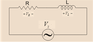
From the above diagram, the total impedance of the circuit is given as:
The phase angle for the circuit is given as:
Hence, the given result is correct.
Want to see more full solutions like this?
Subscribe now to access step-by-step solutions to millions of textbook problems written by subject matter experts!
Students have asked these similar questions
For an inductor in a sine-wave ac circuit,
VL lags iL by 90
VL and iL are in phase
VL leads iL by 90
C=10 μF and e(t)= 35.4 sin(1000t-90°) V
Find the source frequency.
11 - In the series R-L circuit, AA 12 V with a frequency of 50 Hz is applied to the ends of the coil with a resistance of 10 Ω and an inductance of 20 mH.Which of the following is the phase difference (power factor) between the current passing through the circuit and the voltage?A) 0.42B) 0.21C) 0.5D) 0.84E) 0.45
Chapter 12 Solutions
Electronics Fundamentals: Circuits, Devices & Applications
Ch. 12 - In an ac circuit where R=XL, the phase angle is...Ch. 12 - Prob. 2TFQCh. 12 - In an ac series RL circuit, the current and...Ch. 12 - In an ac parallel RL circuit, the inductive...Ch. 12 - In an ac parallel RL circuit, the voltage across...Ch. 12 - The unit siemens is used to measure both...Ch. 12 - Prob. 7TFQCh. 12 - If the power factor of a circuit is 0.5, the...Ch. 12 - Prob. 9TFQCh. 12 - Prob. 10TFQ
Ch. 12 - In a series RL circuit, the resistor voltage Leads...Ch. 12 - Prob. 2STCh. 12 - Prob. 3STCh. 12 - If the frequency is doubled and the resistance is...Ch. 12 - Prob. 5STCh. 12 - Prob. 6STCh. 12 - Prob. 7STCh. 12 - Prob. 8STCh. 12 - Prob. 9STCh. 12 - Prob. 10STCh. 12 - Prob. 11STCh. 12 - Prob. 12STCh. 12 - If a load is purely inductive and the reactive...Ch. 12 - Prob. 14STCh. 12 - Prob. 15STCh. 12 - Determine the cause for each set of symptoms....Ch. 12 - Determine the cause for each set of symptoms....Ch. 12 - Prob. 3TSCCh. 12 - Prob. 4TSCCh. 12 - Prob. 5TSCCh. 12 - Prob. 1PCh. 12 - Prob. 2PCh. 12 - Find the impedance of each circuit in Figure...Ch. 12 - Determine the impedance and phase angle in each...Ch. 12 - In Figure 12-52, determine the impedance at each...Ch. 12 - Determine the values of R and XL in a series RL...Ch. 12 - If the frequency of the source is increased to 1...Ch. 12 - Determine the voltage across the total resistance...Ch. 12 - Find the current for each circuit of Figure 12-50.Ch. 12 - Calculate the total current in each circuit of...Ch. 12 - Determine for the cicutit in Figure 12-53.Ch. 12 - If the inductance in Figure 12-53 is doubled, does...Ch. 12 - Draw the waveforms for Vs,VRandVL in Figure 12-53....Ch. 12 - For the circuit in Figure 12-54, find VRandVL for...Ch. 12 - For the lag circuit in Figure 12-55, determine the...Ch. 12 - Repeat Problem 15 for the lead circuit in Figure...Ch. 12 - What is the impedance for the circuit in Figure...Ch. 12 - Repeat Problem 17 for the following frequencies:...Ch. 12 - At what frequecy does XL equal R in Figure 12-57?Ch. 12 - Find the total current and each branch current in...Ch. 12 - Determine the following quantities in Figure...Ch. 12 - Convert the circuit in Figure 12-60 to an...Ch. 12 - Determine the voltage across each element in...Ch. 12 - Is the circuit in Figure 12-61 predominantly...Ch. 12 - Find the current in each branch and the total...Ch. 12 - In a certain RL circuit, the true power is 100 mW,...Ch. 12 - Determine the true power and the reactive power in...Ch. 12 - What is the power factor in Figure 12-58?Ch. 12 - Determine Ptrue,Pr,Pa, and PF for the circuit in...Ch. 12 - Plot the response curve for the circuit in Figure...Ch. 12 - Using the same procedure as in Problem 30, plot...Ch. 12 - Draw the voltage phasor diagram for each circuit...Ch. 12 - Prob. 33PCh. 12 - Prob. 34PCh. 12 - Determine the voltage across the inductors in...Ch. 12 - Is the circuit in Figure 12-64 predominantly...Ch. 12 - Find the total current in Figure 12-64.Ch. 12 - Determine the phase shift and attenuation...Ch. 12 - Design an ideal inductive switching circuit that...Ch. 12 - Prob. 44PCh. 12 - Prob. 45PCh. 12 - Prob. 46PCh. 12 - Prob. 47PCh. 12 - Open file P12-48. Determine if there is a fault...Ch. 12 - Prob. 49P
Knowledge Booster


Learn more about
Need a deep-dive on the concept behind this application? Look no further. Learn more about this topic, electrical-engineering and related others by exploring similar questions and additional content below.Similar questions
- An RC series circuit has a total impedance of 84 . The resistor has a value of 32 . What is the capacitive reactance of the capacitor? XC=Z2R2arrow_forwardAssume the circuit shown in Figure 17-2 has a power factor of 78%, an apparent power of 374.817 VA, and a frequency of 400 Hz. The inductor has an inductance of 0.0382 H. ETITZVA374.817PF78%ERIRRPELILXLVARsLL0.0382Harrow_forward17. If the resistance of the series RL is increased the magnitude of the phase angle willarrow_forward
- Power factor correction is an adjustment of the electrical circuit in order to change the phase angle near _____ a. 0 b. 100 c. 1arrow_forwardWhat is the angle, theta(in degrees)arrow_forwardCompute the impedance of a series RL circuit with the following values: R = 114 ΩL = 347 mHf = 60 hzarrow_forward
- (#2) Need help calculating the magnitude and phase of H(j*omega), at each of the frequencies. (Just the first one at 100Hz is good steps would be helpful!) Please and thank you. H(s) of the circuit is given.arrow_forwardAn RC series circuit is connected to a 277 volt 60Hz line. the apparent power of the ciruit is 8.2 kVA. what is the impedance of the ciruit?arrow_forwardAssume frequency is 60HZarrow_forward
- In an RL series circuit the frequency is 60Hz, the voltage above the resistor is 60, the inductance is 0.4 H and the angle is 30º. Calculate A) Inductive reactance B) Voltage drop in the inductor C) Current D) The impedancearrow_forwardIn an RL Series circuit with R= 1.2 kN and L= 15 mH coil across an AC source 20v, 10 kHz . The magnitude of the total impedance is Select one: a. NONE OF THESE b. 1526 Ohm c. 2.25 Ohm d. 1.526 Ohmarrow_forwardI need ASAP. Thank you! Find the band pass phase angle (degree) of F1(Hz), F2(Hz), F3(Hz) using the formula below: φo= -tan-1 (ω L/R - 1/ωRC)arrow_forward
arrow_back_ios
SEE MORE QUESTIONS
arrow_forward_ios
Recommended textbooks for you
 Delmar's Standard Textbook Of ElectricityElectrical EngineeringISBN:9781337900348Author:Stephen L. HermanPublisher:Cengage Learning
Delmar's Standard Textbook Of Electricity
Electrical Engineering
ISBN:9781337900348
Author:Stephen L. Herman
Publisher:Cengage Learning
02 - Sinusoidal AC Voltage Sources in Circuits, Part 1; Author: Math and Science;https://www.youtube.com/watch?v=8zMiIHVMfaw;License: Standard Youtube License