
Electric Motor Control
10th Edition
ISBN: 9781133702818
Author: Herman
Publisher: CENGAGE L
expand_more
expand_more
format_list_bulleted
Concept explainers
Videos
Textbook Question
Chapter 12, Problem 4SQ
To answer the following questions refer to Figure 12–10.
When the thermostat contacts close the blower motor starts and the heating elements turn on normally. When the thermostat contacts open, the heating elements turn off and the blower motor stops running immediately. Which of the following could cause the problem?
- a. The thermostat contacts did not open.
- b. The flow switch contacts did not open.
- c. The fan thermostat contacts did not close.
- d. BMR coil is open.
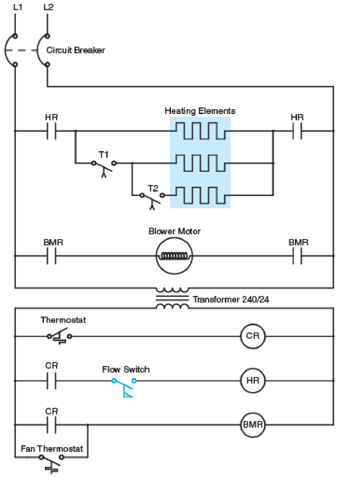
FIG. 12–10 Air flow must be present before heating elements can be energized.
Expert Solution & Answer
Want to see the full answer?
Check out a sample textbook solution
Students have asked these similar questions
A 30- hp squirrel cage induction motor is connected to a 240-volt three phase feeder. The motor is to be replaced with a 50-hp squirrel cage induction motor connected to 480 volts. The motor has a nema code b, a full load current of 49.8 amps, and an sf of 1.10. the present conductors are 3 awg copper with thwn insulation. Are these conductors sufficient to connect to the 50-hp motor or will they have to be replaced
Does the Indoor Fan Motor stop when the control fuses faulty?
A technician reads 24 Volts to a relay coil that is rated 24V, 120 Volts to the input terminal of the relay contacts, but 0 volts to the other side of the relay contacts, which of the following could be the problem
A. A bad set of contacts
B. A bad thermostat
C. A bad high pressure safety switch
D. A bad fan motor
Chapter 12 Solutions
Electric Motor Control
Ch. 12 - Prob. 1SQCh. 12 - Draw a line diagram to show that a green light...Ch. 12 - Draw a one-line diagram showing a bell that will...Ch. 12 - To answer the following questions refer to Figure...Ch. 12 - When the thermostat contacts close, the blower...Ch. 12 - When the thermostat contacts close, the blower...Ch. 12 - When the thermostat contacts close the blower...
Knowledge Booster


Learn more about
Need a deep-dive on the concept behind this application? Look no further. Learn more about this topic, electrical-engineering and related others by exploring similar questions and additional content below.Similar questions
- If pilot lights are to indicate which coil is energized, where should they be connected? Additional auxiliary contacts are not to be used.arrow_forwardTechnician A says when testing the voltage output, if the charging voltage is too high, the cause could be an open field wire from the regulator. Technician B says a loose or glazed drive belt could be the cause of too high charging voltage. Who is correct? A only B only Both A and B Neither A or B Technician A says that poor connection at the generator output wire can cause charging systems problems. Technician B says that many charging system circuits contain a circuit protection device. Who is correct? A only B only Both A and B Neither A or Barrow_forwardIf the compressor and condenser fan motor will not operate but the indoor fan motor is operating,what would be the probable cause of the malfunction.arrow_forward
- 7. Which statement is true for the process-control relay ladder diagram shown in the figure? A. The pressure switch, temperature switch, and push button must be closed for the motor to start. B. With the temperature switch closed, the motor will start once the push button is pressed. C. With the pressure switch closed and the push button released, the motor will start. D. Only the temperature switch has to close for the motor to start.arrow_forward6. A 50-hp DC motor is connected to 250 volts. The motor does not contain a NEMA code. The motor is expected to operate for more than three hours at a time. The conductors are to be copper with type RHW-2 insulation. The motor is located in an area with an ambient temperature of . The two conductors are to be run in conduit. What size conductors should be used to connect this motor? (Note: 1 hp = 746 watts.)arrow_forward2. In the motor control circuit of Figure 11 in your study unit, the operation of any one of the overload relays has which of the following effects?A. The motor only runs two phases.B. The motor operates normally. C. The auxiliary contact M closes. D. The motor stopsarrow_forward
- Select the best answer for each of the following. When the reset button does not reestablish the control circuit after an overload, the probable cause is a. the overload heater is too small. b. the overload trip has not cooled sufficiently. c. the auxiliary contacts are defective. d. the overload heater is burned out.arrow_forward29. The overload relay used to protect each motor - compressor set shall be selected to trip at NOT more than ____ of the motor-compressor rated load current. a. 125% b. 150% c. 140% d. 160%arrow_forwardA 100-HP three-phase squirrel-cage induction motor is connected to 480 volts. The conductors supplying the motor are copper with THW2 insulation. The nameplate lists a full-load running current of 118 amperes, NEMA Code B, and a service factor of 1.00. Current transformers with a ratio of 200:5 are used to reduce the current supplied to the overload heaters. The motor is protected with dual-element time delay fuses. Determine the conductor size, overload heater size using the chart in Figure 34-7, NEMA and IEC starter sizes, and fuse size for this motor.arrow_forward
- A 25-HP, continuous-duty, three-phase squirrel-cage induction motor is connected to a 240-volt line. The conductors are run in conduit to the motor. The motor does not have a NEMA design code listed on the nameplate. The termination temperature rating of the devices is not known. Copper conductors with THWN insulation are to be used for the motor connection. What size conductors should be used?arrow_forwardWhat is the purpose of an air-conditioning control system?arrow_forwardA single-phase electric motor is connected to a 240-volt, 30-ampere circuit. The motor nameplate indicates that the full-load current draw of the motor is 21 amperes. The motor is connected to an inertia load (a large flywheel) that requires several seconds for the motor to accelerate to full speed. Because of the long starting time, the motor causes the circuit breaker to trip before the load has reached full speed. Your job is to connect a resistor in series with the motor during the starting period that will limit the starting current to 90% of the circuit-breaker rating. An ammeter indicates that the motor has a current draw of 64 amperes when power is first applied to the motor. Determine the ohmic value and wattage rating of the resistor that should be connected in series with the motor during the starting period.arrow_forward
arrow_back_ios
arrow_forward_ios
Recommended textbooks for you
 Delmar's Standard Textbook Of ElectricityElectrical EngineeringISBN:9781337900348Author:Stephen L. HermanPublisher:Cengage Learning
 Electricity for Refrigeration, Heating, and Air C...Mechanical EngineeringISBN:9781337399128Author:Russell E. SmithPublisher:Cengage Learning
Delmar's Standard Textbook Of Electricity
Electrical Engineering
ISBN:9781337900348
Author:Stephen L. Herman
Publisher:Cengage Learning
Electricity for Refrigeration, Heating, and Air C...
Mechanical Engineering
ISBN:9781337399128
Author:Russell E. Smith
Publisher:Cengage Learning
Single Phase Induction Motor, How it works ?; Author: Lesics;https://www.youtube.com/watch?v=awrUxv7B-a8;License: Standard Youtube License