
Concept explainers
Videos
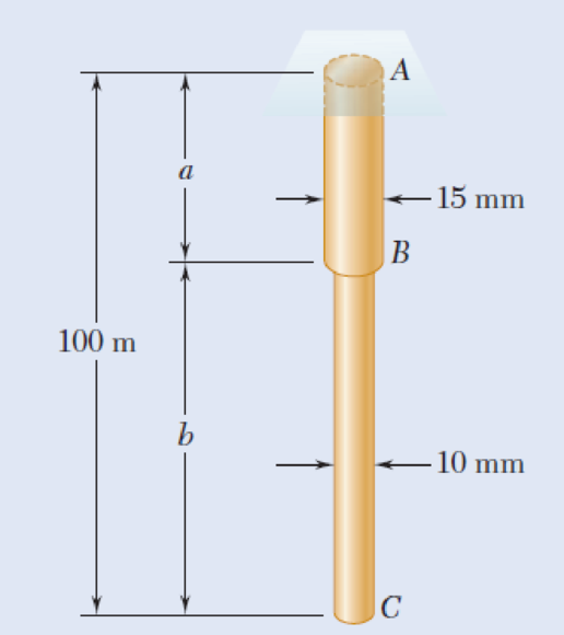
Two brass rods AB and BC, each of uniform diameter, will be brazed together at B to form a nonuniform rod of total length 100 m that will be suspended from a support at A as shown. Knowing that the density of brass is 8470 kg/m3, determine (a) the length of rod AB for which the maximum normal stress in ABC is minimum, (b) the corresponding value of the maximum normal stress.
Fig. P1.6
(a)
The length of brass rod AB such that the maximum normal stress in ABC is minimum.
Answer to Problem 6P
The length of brass rod AB such that the maximum normal stress in ABC is minimum as
Explanation of Solution
Given information:
The total length of the rod is
The length of rod AB is a.
The length of rod BC is
The density of the brass is
The diameter of the rod AB is
The diameter of the rod BC is
Calculation:
Calculate the area
Here,
Substitute
Calculate the area
Here,
Substitute
Calculate the weights
Here,
Substitute
Calculate the weights
Here,
Substitute
Find the force
Here,
Substitute
Find the normal stress acting at point A using the formula:
Here,
Substitute
Find the normal stress acting at point B using the formula:
Here,
Consider
Substitute
Find the length of brass rod AB for the maximum stress in ABC as minimum:
Here,
Substitute
Thus, the length of brass rod AB is
(b)
The value of maximum normal stress of brass rods.
Answer to Problem 6P
The maximum normal stress of brass rods is
Explanation of Solution
Calculation:
Find the maximum normal stress of brass rod using the relation:
Substitute
Substitute
Thus, the maximum normal stress of brass rods is
Want to see more full solutions like this?
Chapter 1 Solutions
MECHANICS OF MATERIALS
Additional Engineering Textbook Solutions
Applied Statics and Strength of Materials (6th Edition)
INTERNATIONAL EDITION---Engineering Mechanics: Statics, 14th edition (SI unit)
Thinking Like an Engineer: An Active Learning Approach (3rd Edition)
Vector Mechanics for Engineers: Statics and Dynamics
Fluid Mechanics: Fundamentals and Applications
Thermodynamics: An Engineering Approach


- Two steel plates are to be held together by means of 16-mm-diameter high-strength steel bolts fitting snugly inside cylindrical brass spacers. Knowing that the average normal stress must not exceed 205 MPa in the bolts and 132 MPa in the spacers, determine the outer diameter of the spacers that yields the most economical and safe design. The outer diameter of the spacers that yields the most economical and safe design is mm.arrow_forwardTwo cylindrical rods, one of steel and the other of brass, are joined at C and restrained by rigid supports at A and E. The steel rod has a length of 300 mm while the brass rod has a length of 200 mm. The diameters of the rods are shown in the figure below. A force of 60 kN is applied at point B of the steel segment. For the loading shown and knowing that modulus of elasticity values for steel and brass are respectively Es = 200 GPa and Eb = 105 GPa, determine a.) The reactions at A and E: RA and RE. b.) The deflection of point C from its original location. how to doarrow_forwardA 5.3-m-long steel rod must not stretch more than 2.71 mm and the normal stress must not exceed 181 MPa when the rod is subjected to a 9.99-kNaxial load. Knowing that E = 199.3 GPa, determine the required radius of the rod in mm. Express your answer in four decimal places.arrow_forward
- A boiler is constructed of 8-mm-thick steel plates that are fastened together at their ends using a butt joint consisting of two 8-mm cover plates and rivets having a diameter of 10 mm and spaced 50 mm apart as shown. If the steam pressure in the boiler is 1.35 MPa, determine (a) the circumferential stress in the boiler’s plate away from the seam, (b) the circumferential stress in the outer cover plate along the rivet line a–a, and (c) the shear stress in the rivets.arrow_forwardA fabric used in air-inflated structures is subjected to a biaxial loading that results in normal stresses ox = 18 ksi and oz = 24 ksi.Knowing that the properties of the fabric can be approximated as E = 12.6 x 10 psi and v = 0.34, determine the change in length of (a) side AB, (b) side BC, (c) diagonal AC.arrow_forwardA steel rod is subjected to a gradually applied load (F) which gave a rise to a maximum stress of 200 MPa. The rod is 250 mm long and one part of its length is square and the remainder is circular with a diameter of 25 mm. If the total strain energy in the rod and modulus elasticity of the material is 1.3 J and 200 GPa, determine the following:1.The applied load F2.The total extension of the bar3.The length of the square portion of the bar4.The suddenly applied load that will induce the same amount of energy 5.The load that falls from a height of 8 mm induces 1,3 J in the bar.arrow_forward
- 6. A strain gage located at C on the surface of bone AB indicates that the average normal stress in the bone is 3.80 MPa when the bone is subjected to two 1200-N forces as shown. Assuming the cross section of the bone at C to be annular and knowing that its outer diameter is 25 mm, determine the inner diameter of the bone’s cross section at C.arrow_forwardA steel plate 5/16 in. thick is embedded in a horizontal concrete slab and is used to anchor a high-strength vertical cable as shown. The diameter of the hole in the plate is 3/4in., the ultimate strength of the steel used is 36 ksi, and the ultimate bonding stress between plate and concrete is 300 psi. Knowing that a factor of safety of 3.60 is desired when P = 2.5 kips, determine (a) the required width a of the plate,(b) the minimum depth b to which a plate of that width should be embedded in the concrete slab. (Neglect the normal stresses betweenthe concrete and the lower end of the plate.)arrow_forwardFor the truss and loading shown, determine the magnitude of the normal stress(in psi) in member CE, knowing that the cross-sectional area of that member is 3.67 in2 if P = 30505 lb, Q = 34758 lb, and y = 7.35 ft. Round off the final answer to two decimal places.arrow_forward
- A 5-kN tensile load will be applied to a 50-m length of steel wire with E = 200 GPa. Determine the smallest diameter wire that can be used, knowing that the normal stress must not exceed 150 MPa and that the increase in length of the wire must not exceed 25 mm.arrow_forwardA fabric used in air-inflated structures is subjected to a biaxial load-ing that results in normal stresses σx=120 MPa and σz =160 MPa. Knowing that the properties of the fabric can be approximated as E=87 GPa and ν= 0.34, determine the change in length of (a) side AB, (b) side BC, (c) diagonal AC.arrow_forwardThe aluminum rod AD is fitted with a jacketthat is used to apply a hydrostatic pressure of5000 psi to the 12-in. portion BC of the rod.Knowing that E = 10.1 × 10⁶ psi and v = 0.36,determine the forces that should be appliedto the ends A and D of the rod if the axialstrain in portion BC of the rod is to remainzero as the hydrostatic pressure is applied.Determine the forces that should be appliedto the ends A and D if the total length AD ofthe rod is to remain unchanged.arrow_forward
 Elements Of ElectromagneticsMechanical EngineeringISBN:9780190698614Author:Sadiku, Matthew N. O.Publisher:Oxford University Press
 Mechanics of Materials (10th Edition)Mechanical EngineeringISBN:9780134319650Author:Russell C. HibbelerPublisher:PEARSON
 Thermodynamics: An Engineering ApproachMechanical EngineeringISBN:9781259822674Author:Yunus A. Cengel Dr., Michael A. BolesPublisher:McGraw-Hill Education
 Control Systems EngineeringMechanical EngineeringISBN:9781118170519Author:Norman S. NisePublisher:WILEY
 Mechanics of Materials (MindTap Course List)Mechanical EngineeringISBN:9781337093347Author:Barry J. Goodno, James M. GerePublisher:Cengage Learning
 Engineering Mechanics: StaticsMechanical EngineeringISBN:9781118807330Author:James L. Meriam, L. G. Kraige, J. N. BoltonPublisher:WILEY