Fundamentals of Electric Circuits
6th Edition
ISBN: 9780078028229
Author: Charles K Alexander, Matthew Sadiku
Publisher: McGraw-Hill Education
bartleby

Concept explainers

bartleby

Videos

Textbook Question
Book Icon
Chapter 12, Problem 71P

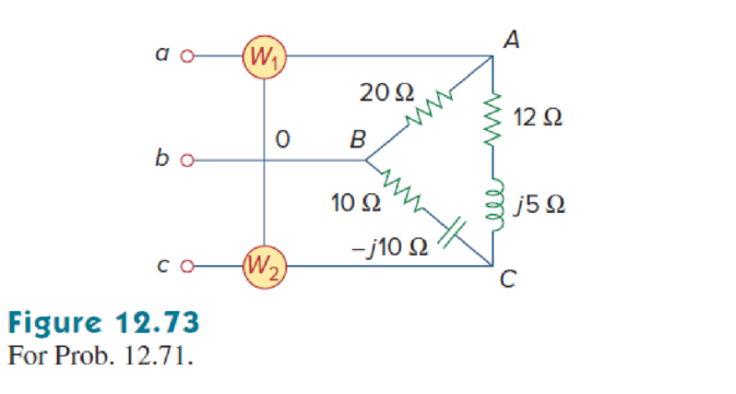
In Fig. 12.73, two wattmeters are properly connected to the unbalanced load supplied by a balanced source such that Chapter 12, Problem 71P, In Fig. 12.73, two wattmeters are properly connected to the unbalanced load supplied by a balanced , example  1 
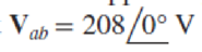
with positive phase sequence.

  1. (a) Determine the reading of each wattmeter.
  2. (b) Calculate the total apparent power absorbed by the load.

Chapter 12, Problem 71P, In Fig. 12.73, two wattmeters are properly connected to the unbalanced load supplied by a balanced , example  2

(a)

Expert Solution
Check Mark
To determine

Find the readings of wattmeter W1 and wattmeter W2.

Answer to Problem 71P

The readings of wattmeter W1 and wattmeter W2 are 2,590W_ and 4,808W_ respectively.

Explanation of Solution

Given data:

Refer to the Figure 12.73 in the textbook, which shows the unbalanced load circuit with two-wattmeters.

The balanced source connected the circuit has the line to line voltage Vab=2080° V.

Formula used:

Consider the positive phase sequence.

Write the expression to find the line to line voltage Vbc.

Vbc=Vp120° (1)

Here,

Vp is the magnitude of the phase voltage.

Write the expression to find the line to line voltage Vca.

Vca=Vp120° (2)

Write the expression to find the line to line current (IAB).

IAB=VabZAB (3)

Here,

Vab is the line to line voltage of a-b source terminal.

ZAB is the line to line impedance of A-B load terminal.

Write the expression to find the line to line to current IBC.

IBC=VbcZBC (4)

Here,

Vbc is the line to line voltage of b-c source terminal.

ZBC is the line to line impedance of B-C load terminal.

Write the expression to find the line to line current ICA.

ICA=VcaZCA                                                                                                    (5)

Here,

Vca is the line to line voltage of c-a source terminal.

ZCA is the line to line impedance of C-A load terminal.

Write the expression to find the line current (IaA).

IaA=IABICA (6)

Write the expression to find the line current (IcC).

IcC=ICAIBC (7)

Write the expression to find the power (P1).

P1=|Vab||IaA|cos(θVabθIaA) (8)

Here,

θVab is the phase angle of the source voltage Vab.

θIaA is the phase angle of the line current IaA.

Write the expression to find the power (P2).

P2=|Vcb||IcC|cos(θVcbθIcC) (9)

Here,

θVcb is the phase angle of the source voltage Vcb.

θIcC is the phase angle of the line current IcC.

Calculation:

The magnitude of the phase voltage Vp is 208V. Re-draw the circuit as shown in Figure 1 with the indication of phase and line currents.

Fundamentals of Electric Circuits, Chapter 12, Problem 71P

Substitute 208V for Vp in equation (1) to find the voltage Vbc.

Vbc=208120°V

Substitute 208V for Vp in equation (2) to find the voltage Vca.

Vca=208120°V

Substitute 2080°V for Vab and 20Ω for ZAB in equation (3) to find the current IAB.

IAB=2080°V20Ω=10.40°VΩ=10.40°A               {VΩ=A}

Substitute 208120°V for Vbc and 10j10Ω for ZBC in equation (4) to find the IBCIBC=208120°V10j10Ω=208120°V14.142145°Ω=20814.1421(120°(45°)) A               {VΩ=A}=14.70875° A

Substitute 208120°V for Vca and 12+j5Ω for ZCA in equation (5) to find the current ICA.

ICA=208120°V12+j5Ω=208120°V1322.62°Ω=20813(120°22.62°)A               {VΩ=A}=1697.38°A

Substitute 10.40°A for IAB and 1697.38°A for ICA in equation (6) to find the current IaA.

IaA=(10.40°A)(1697.38°A)=(10.4+0jA)(2.055+j15.867A)=12.455j15.867A=20.17151.869°AIaA20.17151.87°A

Substitute 1697.38°A for ICA and 14.70875°A for IBC in equation (7) to find (IcC).

IcC=(1697.38°A)(14.70875°A)=(2.0551+j15.867A)(3.8067j14.206)A=5.8617+j30.073A=30.64101.03°A

Substitute 208V for Vab, 20.171A for IaA, 0° for θVab and 51.87° for θIaA in equation (8) to find P1.

P1=|208V||20.171A|cos(0°(51.87°))=(208V)(20.171A)cos(51.87°)=(4,195.568VA)(0.61744)=2,590.51WP12,590kW

Write the expression to find the voltage Vcb is,

Vcb=Vbc180° (10)

Substitute 208120°V for Vbc in above equation to find the line to line source voltage Vcb.

Vcb=(208120°V)(180°)=208(120°+180°)V=20860°V

Substitute 208V for Vcb, 30.64A for IcC, 60° for θVcb and 101.03° for θIcC in equation (9) to find P2.

P2=|208V||30.64A|cos(60°101.03°)=(208V)(30.64A)cos(41.03)=(6,373.12VA)(0.7543)=4,807.244WP24,808W

Conclusion:

Thus, the readings of wattmeter W1 and wattmeter W2 are 2,590W_ and 4,808W_ respectively.

(b)

Expert Solution
Check Mark
To determine

Find the total apparent power absorbed by the unbalanced load.

Answer to Problem 71P

The total apparent power absorbed by the unbalanced load is 8,335VA_.

Explanation of Solution

Formula used:

Write the expression to find the total real power is,

PT=P1+P2 (11)

Here,

P1 and P2 are the readings of the wattmeters.

Write the expression to find the total reactive power is,

QT=3(P2P1) (12)

Write the expression to find the total complex power is,

ST=PT+jQT (13)

Write the expression to find the magnitude of the total apparent power is,

ST=|ST| (14)

Here,

ST is the total complex power.

Calculation:

Substitute 2,590.51W for P1 and 4,807.244 W for P2 in equation (11) to find PT.

PT=(2,590.51W)+(4,807.244 W)=7,397.754W

Substitute 2,590.51W for P1 and 4,807.244 W for P2 in equation (12) to find QT.

QT=3(4,807.244 W2,590.51W)=3,840.4959W=3,840.4959VAR{1W=1VA}

Substitute 3,840.4959VAR for QT, and 7,397.754W for PT in equation (13) to find ST.

ST=7,397.754W+j3,840.4959VAR=7,397.754VA+j3,840.4959VAR{1W=1VA}=8,335.23627.435°VAST8,33527.44°VA

Substitute 8,33527.44°VA for ST in equation (14) to find ST.

ST=|8,33527.44°VA|=8,335VA

Conclusion:

Thus, the total apparent power absorbed by the unbalanced load is 8,335VA_.

Want to see more full solutions like this?

Subscribe now to access step-by-step solutions to millions of textbook problems written by subject matter experts!
Students have asked these similar questions
A balanced Δ - connected load having a 15 Ω resistance in each leg is connected to a three -phase , four wires, Y-connected ABC sequence AC generator, if the line volatge EAB=, calculate  1. The phase voltages of the generator 2. The phase voltages of the load 3. The phase currents of the load  4. The line currents
A balanced Y - connected load having a 25 Ω resistance in each leg is connected to a three -phase , four wires, Y-connected ABC sequence AC generator, if the line volatge EAB=, calculate  1. The phase voltages of the generator 2. The phase voltages of the load 3. The phase currents of the load  4. The line currents
A balanced star-connected load having an impedance (15+j20) ohms per phase is connected to a three-phase, 440 V, 50 Hz supply. Find the line currents and the power absorbed by the load. Assume negative phase sequence.

Chapter 12 Solutions

Fundamentals of Electric Circuits

Ch. 12.9 - Prob. 11PPCh. 12.9 - For the unbalanced circuit in Fig. 12.32, use...Ch. 12.10 - Repeat Example 12.13 for the network in Fig. 12.24...Ch. 12.10 - Let the line voltage VL = 208 V and the wattmeter...Ch. 12.10 - If the load in Fig. 12.35 is delta-connected with...Ch. 12 - What is the phase sequence of a three-phase motor...Ch. 12 - If in an acb phase sequence, , then Vcn is:Ch. 12 - Which of these is not a required condition for a...Ch. 12 - Prob. 4RQCh. 12 - Prob. 5RQCh. 12 - In a Y-Y system, a line voltage of 220 V produces...Ch. 12 - In a - system, a phase voltage of 100 V produces a...Ch. 12 - When a Y-connected load is supplied by voltages in...Ch. 12 - Prob. 9RQCh. 12 - Prob. 10RQCh. 12 - If Vab = 400 V in a balanced Y-connected...Ch. 12 - What is the phase sequence of a balanced...Ch. 12 - Given a balanced Y-connected three-phase generator...Ch. 12 - A three-phase system with abc sequence and VL =...Ch. 12 - For a Y-connected load, the time-domain...Ch. 12 - Using Fig. 12.41, design a problem to help other...Ch. 12 - Obtain the line currents in the three-phase...Ch. 12 - In a balanced three-phase Y-Y system, the source...Ch. 12 - A balanced Y-Y four-wire system has phase voltages...Ch. 12 - For the circuit in Fig. 12.43, determine the...Ch. 12 - In the Y- system shown in Fig. 12.44, the source...Ch. 12 - Using Fig. 12.45, design a problem to help other...Ch. 12 - In the balanced three-phase Y- system in Fig....Ch. 12 - Obtain the line currents in the three-phase...Ch. 12 - The circuit in Fig. 12.48 is excited by a balanced...Ch. 12 - A balanced delta-connected load has a phase...Ch. 12 - A positive sequence wye-connected source where ,...Ch. 12 - If Van = 22060 V in the network of Fig. 12.49,...Ch. 12 - For the - circuit of Fig. 12.50, calculate the...Ch. 12 - Prob. 20PCh. 12 - Three 440-V generators form a delta-connected...Ch. 12 - Find the line currents IaA, IbB, and IcC in the...Ch. 12 - A balanced delta connected source is connected to...Ch. 12 - A balanced delta-connected source has phase...Ch. 12 - In the circuit of Fig. 12.54, if , , , find the...Ch. 12 - Using Fig. 12.55, design a problem to help other...Ch. 12 - A -connected source supplies power to a...Ch. 12 - The line-to-line voltages in a Y-load have a...Ch. 12 - A balanced three-phase Y- system has V rms and Z =...Ch. 12 - In Fig. 12.56, the rms value of the line voltage...Ch. 12 - A balanced delta-connected load is supplied by a...Ch. 12 - Design a problem to help other students better...Ch. 12 - A three-phase source delivers 4.8 kVA to a...Ch. 12 - A balanced wye-connected load with a phase...Ch. 12 - Three equal impedances, 60 + j30 each, are...Ch. 12 - A 4200-V, three-phase transmission line has an...Ch. 12 - The total power measured in a three-phase system...Ch. 12 - Given the circuit in Fig. 12.57 below, find the...Ch. 12 - Find the real power absorbed by the load in Fig....Ch. 12 - For the three-phase circuit in Fig. 12.59, find...Ch. 12 - A balanced delta-connected load draws 5 kW at a...Ch. 12 - A balanced three-phase generator delivers 7.2 kW...Ch. 12 - Refer to Fig. 12.48. Obtain the complex power...Ch. 12 - A three-phase line has an impedance of 1 + j3 per...Ch. 12 - A balanced wye-connected load is connected to the...Ch. 12 - A three-phase load consists of three 100-...Ch. 12 - The following three parallel-connected three-phase...Ch. 12 - A balanced, positive-sequence wye-connected source...Ch. 12 - Each phase load consists of a 20- resistor and a...Ch. 12 - A balanced three-phase source with VL = 240 V rms...Ch. 12 - Consider the wye-delta system shown in Fig. 12.60....Ch. 12 - A four-wire wye-wye circuit has...Ch. 12 - Using Fig. 12.61, design a problem that will help...Ch. 12 - A balanced three-phase Y-source with VP = 880 V...Ch. 12 - A three-phase supply, with the line-to-line...Ch. 12 - Using Fig. 12.63, design a problem to help other...Ch. 12 - Determine the line currents for the three-phase...Ch. 12 - Solve Prob. 12.10 using PSpice or MultiSim. For...Ch. 12 - The source in Fig. 12.65 is balanced and exhibits...Ch. 12 - Use PSpice or MultiSim to determine Io in the...Ch. 12 - Given the circuit in Fig. 12.67, use PSpice or...Ch. 12 - Using Fig. 12.68, design a problem to help other...Ch. 12 - Use PSpice or MultiSim to find currents IaA and...Ch. 12 - For the circuit in Fig. 12.58, use PSpice or...Ch. 12 - A balanced three-phase circuit is shown in Fig....Ch. 12 - A three-phase, four-wire system operating with a...Ch. 12 - As shown in Fig. 12.72, a three-phase four-wire...Ch. 12 - Meter readings for a three-phase wye-connected...Ch. 12 - A certain store contains three balanced...Ch. 12 - The two-wattmeter method gives P1=1200W and...Ch. 12 - In Fig. 12.73, two wattmeters are properly...Ch. 12 - If wattmeters W1 and W2 are properly connected...Ch. 12 - For the circuit displayed in Fig. 12.74, find the...Ch. 12 - Predict the wattmeter readings for the circuit in...Ch. 12 - Prob. 75PCh. 12 - Show that the I2R losses will be higher for a...Ch. 12 - A three-phase generator supplied 10 kVA at a power...Ch. 12 - Prob. 78CPCh. 12 - A balanced three-phase generator has an abc phase...Ch. 12 - A balanced three-phase source furnishes power to...Ch. 12 - A professional center is supplied by a balanced...Ch. 12 - A balanced three-phase system has a distribution...Ch. 12 - A commercially available three-phase inductive...Ch. 12 - Figure 12.76 displays a three-phase...Ch. 12 - Design a three-phase heater with suitable...Ch. 12 - For the single-phase three-wire system in Fig....Ch. 12 - Consider the single-phase three-wire system shown...
Knowledge Booster
Background pattern image
Electrical Engineering
Learn more about
Need a deep-dive on the concept behind this application? Look no further. Learn more about this topic, electrical-engineering and related others by exploring similar questions and additional content below.
Similar questions
SEE MORE QUESTIONS
Recommended textbooks for you
Text book image
Power System Analysis and Design (MindTap Course ...
Electrical Engineering
ISBN:9781305632134
Author:J. Duncan Glover, Thomas Overbye, Mulukutla S. Sarma
Publisher:Cengage Learning
What is the Difference Between Single Phase and Three Phase???; Author: Electrician U;https://www.youtube.com/watch?v=FEydcr4wJw0;License: Standard Youtube License