Fundamentals of Electric Circuits
6th Edition
ISBN: 9780078028229
Author: Charles K Alexander, Matthew Sadiku
Publisher: McGraw-Hill Education
bartleby

Concept explainers

bartleby

Videos

Textbook Question
Book Icon
Chapter 12, Problem 87CP

Consider the single-phase three-wire system shown in Fig. 12.78. Find the current in the neutral wire and the complex power supplied by each source. Take Vs as a 220∠0°-V, 60-Hz source.
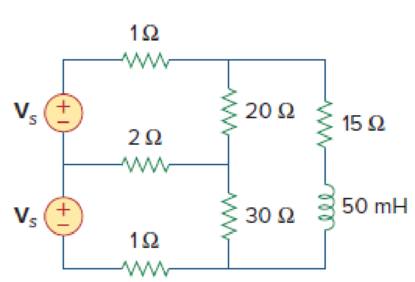
Chapter 12, Problem 87CP, Consider the single-phase three-wire system shown in Fig. 12.78. Find the current in the neutral

Figure 12.78

Expert Solution & Answer
Check Mark
To determine

Calculate the complex power supplied by each source and the current passing through the neutral wire.

Answer to Problem 87CP

The current in the neutral wire is 2.77176.6°A, and the complex power absorbed by each source are 4.581+j2.604 kVA and 3.971+j2.64kVA.

Explanation of Solution

Given data:

Refer to Figure 12.78 in the textbook for a single phase three wire system.

The source voltage is 2200°V.

The supply frequency is 60Hz.

Formula used:

Write the expression to find the complex power S1.

S1=V1I1*        (1)

Here,

V1 is the voltage in the form of complex number,

I1* is the complex conjugate of the current I1.

Write the expression to find the complex power S2.

S2=V2I2*        (2)

Here,

V2 is the voltage in the form of complex number,

I2* is the complex conjugate of the current I2.

Write the expression to find the inductance reactance in ohms.

XL=jωL        (3)

Here,

ω is the angular frequency, and

L is the inductance.

Write the expression to find the angular frequency.

ω=2πf        (4)

Here,

f is the supply frequency.

Calculation:

Substitute 60Hz for f in equation (4) to find ω.

ω=2π(60Hz)=376.99rads377rads

Substitute 377rads for ω, and 50mH for L in equation (3) to find the inductance (L).

XL=j(377rads)(50mH)=j(377rads)(50×103H){1mH=1×10³H}=18.85Ω{1Ω=1Hs}

Modify the given figure with the assumed current directions as shown in Figure.1.

Fundamentals of Electric Circuits, Chapter 12, Problem 87CP

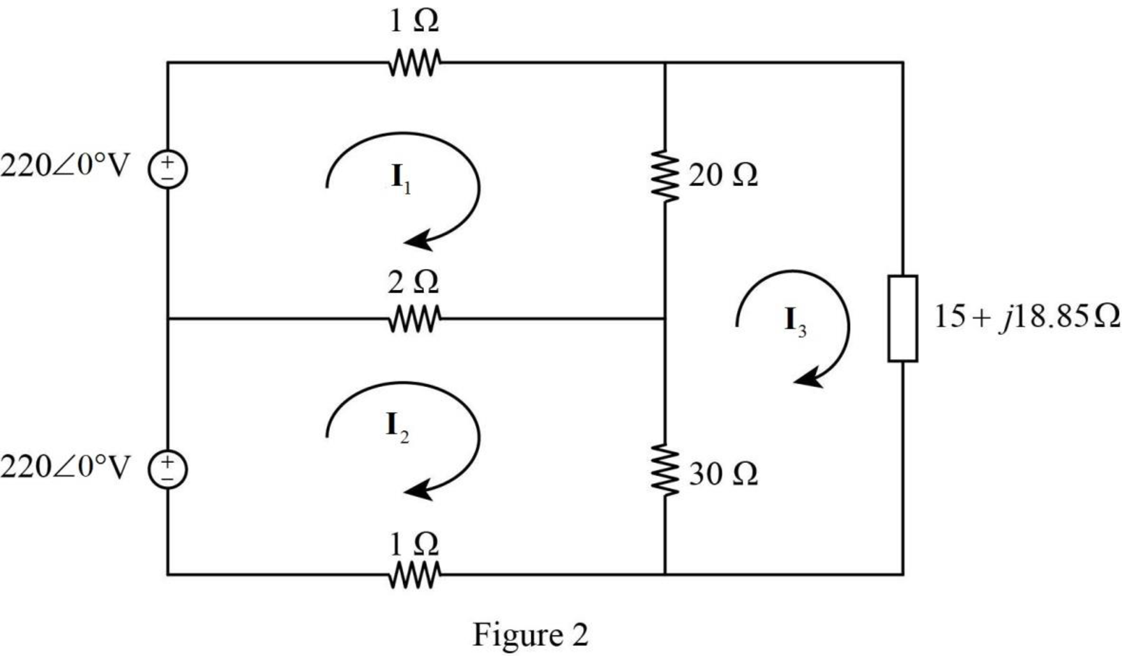
Apply Kirchhoff’s voltage law to loop 1of current I1 in Figure 1.

2200°+I1+20(I1I3)+2(I1I2)=0I1+20I120I3+2I12I2=2200°

23I12I220I3=220        (5)

Apply Kirchhoff’s voltage law to loop 2 of current I2 in Figure 1.

2200°+2(I2I1)+30(I2I3)+I2=02I22I1+30I230I3+I2=2200°

2I1+33I230I3=220        (6)

Apply Kirchhoff’s voltage law to loop 3 of current I3 in Figure 1.

20(I3I1)+(15+j18.85)I3+30(I3I2)=020I320I1+15I3+j18.85I3+30I330I2=0

20I130I2+65I3+j18.85I3=0

20I130I2+(65+j18.85)I3=0        (7)

Represent the equation (5) (6) and (7) in matrix form.

[2322023330203065+j18.85][I1I2I3]=[2202200]

Obtain the value of determinants as follows.

Δ=|2322023330203065+j18.85|=[23[33(65+j18.85)(30)(30)](2)[2(65+j18.85)(20)(30)]20[(2)(30)(20)(33)]]Δ=12,775+j14,231.75

Δ1=|220220220333003065+j18.85|=220[33(65+j18.85)900](2)[220(65+j18.85)0]20[220(30)]Δ1=434500+j145145

Δ2=|232202022203020065+j18.85|=23[220(65+j18.85)0]220[2(65+j18.85)(20)(30)]20(0220(20))Δ2=401500+j103675

Δ3=|23222023322020300|=23[0220(30)](2)[0(20)×(220)]+220[(2)(30)(33)(20)]Δ3=319000

Write the expression to find the currents, I1, I2 , I3 and In using Cramer’s rule.

I1=Δ1Δ        (8)

I2=Δ2Δ        (9)

I3=Δ3Δ        (10)

In=I2I1        (11)

Substitute 434500+j145145 for Δ1 and 12,775+j14,231.75 for Δ in equation (8) to find I1.

I1=434500+j14514512,775+j14,231.75 A=458101.86718.471°19124.41748.087°A=23.953829.616°A

I1=20.8245j11.837 A

Substitute 401500+j103675 for Δ2, and 12,775+j14,231.75 for Δ in equation (9) to find the current I2.

I2=401500+j10367512775+j14,231.75 A=414669.453514.478°19124.41748.087° A=21.682733.609° A

I2=18.0581j12.0019 A

Substitute 319000 for Δ3, and 12,775+j14,231.75 for Δ in equation (10) to find the current I3.

I3=31900012775+j14,231.75A=31900019124.41748.087°A=16.680248.087°AI3=11.1423j12.4128 A

Substitute 18.0581j12.0019 A for I2, and 20.8245j11.837 A for I1 in equation (11) to find the current In.

In=(18.0581j12.0019 A)(20.8245j11.837 A)In=2.7664j0.1649 AIn=2.7713176.588°AIn2.77176.6°A

Thus, the neutral current is 2.77176.6°A.

Substitute 220V for V1, and 20.8245+j11.837 A for I1* in equation (1) to find S1.

S1=(220V)(20.8245+j11.837 A)      {I1=20.8245j11.837 AI1*=20.8245+j11.837 A}=4581.39+j2604.14 VAS1=4.581+j2.604 kVA

Substitute 220V for V2, and 18.0581j12.0019 A for I2* in equation (2) to find S2.

S2=(220V)(18.0581j12.0019 A)=3972.782+j2640.418VAS23.971+j2.64kVA

Conclusion:

Thus, the current in the neutral wire is 2.77176.6°A, and the complex power absorbed by each source are 4.581+j2.604 kVA and 3.971+j2.64kVA.

Want to see more full solutions like this?

Subscribe now to access step-by-step solutions to millions of textbook problems written by subject matter experts!
Students have asked these similar questions
A balanced three-phase ∆- connected source has a line voltage 120 V. It is connected to a load via a three-wiretransmission line. The per-phase impedance of the ∆-connected load is 30 + j120 Ω. The impedance of each wireof the transmission line is 2 + j4 Ω.How much power is dissipated by the load? How much power is dissipated in transmission line? Power factor of load?
2. Solve the following problem: A THREE-PHASE PLANT CONSUMES 600 KVA, WITH A VOLTAGE OF 2400 VOLTS AND A POWER FACTOR OF 0.8 BEHIND. a) DETERMINE THE EQUIVALENT DELTA IMPEDANCE OF THE PLANT. b) IF THE PLANT WERE A STAR, CALCULATE THE RESISTANCE, REACTANCE AND THE CORRESPONDING PASSIVE ELEMENT.
8) If Vab = 221 Vrms in a balanced Y-connected three-phase generator, find the magnitude of the phase-a voltage (in Vrms), assuming the phase sequence is acb.

Chapter 12 Solutions

Fundamentals of Electric Circuits

Ch. 12.9 - Prob. 11PPCh. 12.9 - For the unbalanced circuit in Fig. 12.32, use...Ch. 12.10 - Repeat Example 12.13 for the network in Fig. 12.24...Ch. 12.10 - Let the line voltage VL = 208 V and the wattmeter...Ch. 12.10 - If the load in Fig. 12.35 is delta-connected with...Ch. 12 - What is the phase sequence of a three-phase motor...Ch. 12 - If in an acb phase sequence, , then Vcn is:Ch. 12 - Which of these is not a required condition for a...Ch. 12 - Prob. 4RQCh. 12 - Prob. 5RQCh. 12 - In a Y-Y system, a line voltage of 220 V produces...Ch. 12 - In a - system, a phase voltage of 100 V produces a...Ch. 12 - When a Y-connected load is supplied by voltages in...Ch. 12 - Prob. 9RQCh. 12 - Prob. 10RQCh. 12 - If Vab = 400 V in a balanced Y-connected...Ch. 12 - What is the phase sequence of a balanced...Ch. 12 - Given a balanced Y-connected three-phase generator...Ch. 12 - A three-phase system with abc sequence and VL =...Ch. 12 - For a Y-connected load, the time-domain...Ch. 12 - Using Fig. 12.41, design a problem to help other...Ch. 12 - Obtain the line currents in the three-phase...Ch. 12 - In a balanced three-phase Y-Y system, the source...Ch. 12 - A balanced Y-Y four-wire system has phase voltages...Ch. 12 - For the circuit in Fig. 12.43, determine the...Ch. 12 - In the Y- system shown in Fig. 12.44, the source...Ch. 12 - Using Fig. 12.45, design a problem to help other...Ch. 12 - In the balanced three-phase Y- system in Fig....Ch. 12 - Obtain the line currents in the three-phase...Ch. 12 - The circuit in Fig. 12.48 is excited by a balanced...Ch. 12 - A balanced delta-connected load has a phase...Ch. 12 - A positive sequence wye-connected source where ,...Ch. 12 - If Van = 22060 V in the network of Fig. 12.49,...Ch. 12 - For the - circuit of Fig. 12.50, calculate the...Ch. 12 - Prob. 20PCh. 12 - Three 440-V generators form a delta-connected...Ch. 12 - Find the line currents IaA, IbB, and IcC in the...Ch. 12 - A balanced delta connected source is connected to...Ch. 12 - A balanced delta-connected source has phase...Ch. 12 - In the circuit of Fig. 12.54, if , , , find the...Ch. 12 - Using Fig. 12.55, design a problem to help other...Ch. 12 - A -connected source supplies power to a...Ch. 12 - The line-to-line voltages in a Y-load have a...Ch. 12 - A balanced three-phase Y- system has V rms and Z =...Ch. 12 - In Fig. 12.56, the rms value of the line voltage...Ch. 12 - A balanced delta-connected load is supplied by a...Ch. 12 - Design a problem to help other students better...Ch. 12 - A three-phase source delivers 4.8 kVA to a...Ch. 12 - A balanced wye-connected load with a phase...Ch. 12 - Three equal impedances, 60 + j30 each, are...Ch. 12 - A 4200-V, three-phase transmission line has an...Ch. 12 - The total power measured in a three-phase system...Ch. 12 - Given the circuit in Fig. 12.57 below, find the...Ch. 12 - Find the real power absorbed by the load in Fig....Ch. 12 - For the three-phase circuit in Fig. 12.59, find...Ch. 12 - A balanced delta-connected load draws 5 kW at a...Ch. 12 - A balanced three-phase generator delivers 7.2 kW...Ch. 12 - Refer to Fig. 12.48. Obtain the complex power...Ch. 12 - A three-phase line has an impedance of 1 + j3 per...Ch. 12 - A balanced wye-connected load is connected to the...Ch. 12 - A three-phase load consists of three 100-...Ch. 12 - The following three parallel-connected three-phase...Ch. 12 - A balanced, positive-sequence wye-connected source...Ch. 12 - Each phase load consists of a 20- resistor and a...Ch. 12 - A balanced three-phase source with VL = 240 V rms...Ch. 12 - Consider the wye-delta system shown in Fig. 12.60....Ch. 12 - A four-wire wye-wye circuit has...Ch. 12 - Using Fig. 12.61, design a problem that will help...Ch. 12 - A balanced three-phase Y-source with VP = 880 V...Ch. 12 - A three-phase supply, with the line-to-line...Ch. 12 - Using Fig. 12.63, design a problem to help other...Ch. 12 - Determine the line currents for the three-phase...Ch. 12 - Solve Prob. 12.10 using PSpice or MultiSim. For...Ch. 12 - The source in Fig. 12.65 is balanced and exhibits...Ch. 12 - Use PSpice or MultiSim to determine Io in the...Ch. 12 - Given the circuit in Fig. 12.67, use PSpice or...Ch. 12 - Using Fig. 12.68, design a problem to help other...Ch. 12 - Use PSpice or MultiSim to find currents IaA and...Ch. 12 - For the circuit in Fig. 12.58, use PSpice or...Ch. 12 - A balanced three-phase circuit is shown in Fig....Ch. 12 - A three-phase, four-wire system operating with a...Ch. 12 - As shown in Fig. 12.72, a three-phase four-wire...Ch. 12 - Meter readings for a three-phase wye-connected...Ch. 12 - A certain store contains three balanced...Ch. 12 - The two-wattmeter method gives P1=1200W and...Ch. 12 - In Fig. 12.73, two wattmeters are properly...Ch. 12 - If wattmeters W1 and W2 are properly connected...Ch. 12 - For the circuit displayed in Fig. 12.74, find the...Ch. 12 - Predict the wattmeter readings for the circuit in...Ch. 12 - Prob. 75PCh. 12 - Show that the I2R losses will be higher for a...Ch. 12 - A three-phase generator supplied 10 kVA at a power...Ch. 12 - Prob. 78CPCh. 12 - A balanced three-phase generator has an abc phase...Ch. 12 - A balanced three-phase source furnishes power to...Ch. 12 - A professional center is supplied by a balanced...Ch. 12 - A balanced three-phase system has a distribution...Ch. 12 - A commercially available three-phase inductive...Ch. 12 - Figure 12.76 displays a three-phase...Ch. 12 - Design a three-phase heater with suitable...Ch. 12 - For the single-phase three-wire system in Fig....Ch. 12 - Consider the single-phase three-wire system shown...
Knowledge Booster
Background pattern image
Electrical Engineering
Learn more about
Need a deep-dive on the concept behind this application? Look no further. Learn more about this topic, electrical-engineering and related others by exploring similar questions and additional content below.
Similar questions
SEE MORE QUESTIONS
Recommended textbooks for you
Text book image
Power System Analysis and Design (MindTap Course ...
Electrical Engineering
ISBN:9781305632134
Author:J. Duncan Glover, Thomas Overbye, Mulukutla S. Sarma
Publisher:Cengage Learning
What is the Difference Between Single Phase and Three Phase???; Author: Electrician U;https://www.youtube.com/watch?v=FEydcr4wJw0;License: Standard Youtube License