
Concept explainers
Videos
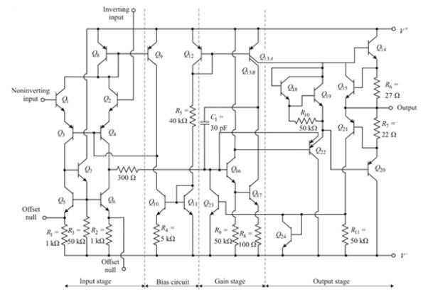
The output resistance of the 741 op-amp if
Answer to Problem 13.24P
The output resistance is
Explanation of Solution
Given:
Consider the 741 op-amp having bias voltage ±5 V
Calculation:
The resistance at
And the output resistance is defined as
Now for solving equation (1) we have
Assuming series resistance of
Where,
And
Where,
The collector current in
The reference current is.
The collector current in
Assuming
And from equation (7),
Now, the current
And the current
Now the resistance
The resistance
Now from the equation (5),
Now from equation (4),
From the equation (3),
Now from the equation (1),
Now from the equation (2),
Want to see more full solutions like this?
Chapter 13 Solutions
Microelectronics: Circuit Analysis and Design


- Op amp and diodes are ideal. Derive Vout and sketch the transfer curve of Vin vs Vout. Please show complete solution.arrow_forwardMake a circuit using a 741 op-amp chip. The required specs of the circuit are: input impedance 500 Ohm, amplitude gain 20arrow_forwardThe ac equivalent circuit for an amplifier is shown. Assume the capacitors have infinite value, RI =750Ω, RB =100 kΩ, RC =100 kΩ, and R3 =100 kΩ. Calculate the input resistance and output resistance for the amplifier if the BJT Q-point is (75 μA, 10 V). Assume βo =100 and VA =75 V.arrow_forward
- Calculate the sensitivity if the RTD temperature is 381.9 oC and Resistance as 397.6 ohms.arrow_forward- Compute voltage peak of the input. Is it equal to what you are expecting base from the setvalues of your VAC source? - Compute voltage peak of the output. Is it equal to what you are expecting base from the setvalues of your VAC source?arrow_forwardThe fixed bias circuit shown in figure uses a silicon transistor with VBE = 0.7V. Find the collector current, IC (if β of transistor is 60)arrow_forward
- Book:Operational amplifiers and Linear integrated circuits Chap#03arrow_forwardCompute voltage peak of the input. Is it equal to what you are expecting base from the set values of your VAC source? Compute voltage peak of the output. Is it equal to what you are expecting base from the set values of your VAC source?arrow_forwarda. IcQ. b. VCEQ. c. Locate the Q-point on the output characteristics. d. Draw the AC equivalent circuit of the above bias network. R1=100kOhms R2=17kOhmsarrow_forward
- 1. For the circuits shown below, if A=∞, Calculate a) The overall input resistance, Rin b) The output resistance, Rout c) Overall voltage gain (vo/vs)arrow_forwardFigure Q3 shows a single stage transistor amplifier driven by a signal voltage source Vi. Determine the operating (Q) point if β = 100 and VBE = 0.7V.arrow_forwardThe combined circuit Using BJT as a switch combine with BJT as an amplifier so calculate: a. Vin b. Voutarrow_forward
 Introductory Circuit Analysis (13th Edition)Electrical EngineeringISBN:9780133923605Author:Robert L. BoylestadPublisher:PEARSON
 Delmar's Standard Textbook Of ElectricityElectrical EngineeringISBN:9781337900348Author:Stephen L. HermanPublisher:Cengage Learning
 Programmable Logic ControllersElectrical EngineeringISBN:9780073373843Author:Frank D. PetruzellaPublisher:McGraw-Hill Education
 Fundamentals of Electric CircuitsElectrical EngineeringISBN:9780078028229Author:Charles K Alexander, Matthew SadikuPublisher:McGraw-Hill Education
 Electric Circuits. (11th Edition)Electrical EngineeringISBN:9780134746968Author:James W. Nilsson, Susan RiedelPublisher:PEARSON
 Engineering ElectromagneticsElectrical EngineeringISBN:9780078028151Author:Hayt, William H. (william Hart), Jr, BUCK, John A.Publisher:Mcgraw-hill Education,