
Concept explainers
Videos
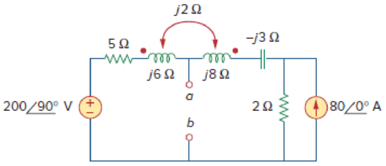
Obtain the Thevenin equivalent circuit for the circuit in Fig. 13.83 at terminals a-b.
Calculate the Thevenin equivalent to the circuit at terminals a-b.
Answer to Problem 14P
TheThevenin equivalent circuit parameters are
Explanation of Solution
Given data:
Refer to Figure 13.83 in the textbook for the circuit with coupled coils.
Consider that the value of the source voltage.
Calculation:
Calculate the Thevenin voltage.
Modify the Figure 13.83 by converting the current source
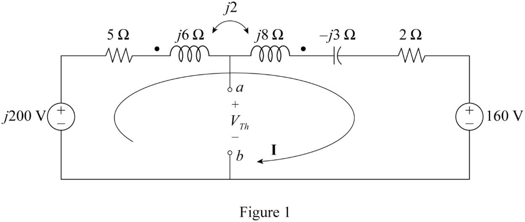
Consider that the two coils are connected series aiding.
Substitute
Apply Kirchhoff's voltage law to the loop 1 contains current
Substitute
Re-arrange the equation.
From Figure 1, consider the following expression using Kirchhoff's voltage law.
Re-arrange the Equation.
Substitute Equation (1) in (2).
Simplify the equation as follows.
To obtain Thevenin impedance
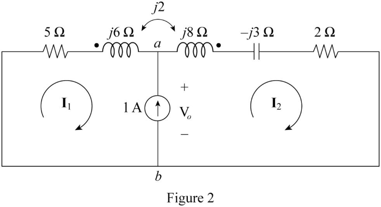
In Figure 2, consider that the loops 1 and 2 contain the currents
Write the Kirchhoff's voltage law expression to Figure 2 using super mesh analysis.
From Figure 2, write the current expression.
Substitute
Apply Kirchhoff's voltage law to the loop 1 contains current
Re-arrange the equation.
Substitute Equation (4) in (5).
Write the expression for Thevenin’s equivalent impedance.
Substitute
Conclusion:
Thus, the Thevenin equivalent circuit parameters are
Want to see more full solutions like this?
Chapter 13 Solutions
Fundamentals of Electric Circuits
Additional Engineering Textbook Solutions
Principles Of Electric Circuits
ANALYSIS+DESIGN OF LINEAR CIRCUITS(LL)
Principles and Applications of Electrical Engineering
Electrical Engineering: Principles & Applications (7th Edition)
Loose Leaf for Engineering Circuit Analysis Format: Loose-leaf
Electronics Fundamentals: Circuits, Devices & Applications


- A choking coil having a resistance of 20 Ω and an inductance of 0.07 henry is connected with a capacitor of 60 μF capacitance which is in series with a resistor of 50 Ω. Calculate the total current and the phase angle when this arrangement is connected to 200-V, 50 Hz mains.arrow_forwardA coil of inductance 159.2 mH and resistance 40 ohms is connected in parallel with a 30 µF capacitor across a 240 V, 50 Hz supply.Calculate(a) Current in the coil and its phase angle (b) Current in the capacitor and its phase angle, (c) Supply current and its phase angle, (d) Circuit impedance, arrow_forwardWhat is the impedance of a transformer coil that has 340' of #18 copper wire and an inductance of 70mH at 60Hz? 1000’ of #18 copper wire is 16 ohms.arrow_forward
- Calculate the equivalent impedance of a circuit where a coil of (5H, angle 53.2 Deg.) ohms is connected in parallel with a capacitive reactance of 6.25 ohms.arrow_forwardA coil has a resistance of 4 and an inductance of 9.55 mH. Calculate (a) the reactance, (b) the impedance, and (c) the current taken from a 240V, 50 Hz supply. Determine also the phase angle between the supply voltage and currentarrow_forward34. A 33 kV, 50 Hz network has a capacitance to neutral of 1.0 µF per phase. Calculate the reactance of an arc suppression coil suitable for the system to avoid adverse effect of arching ground.arrow_forward
- The impedance value for a network containing the utility and a transformer is Select one: None of these Zt=√(〖((Ztranformer)〗2+〖((Zutility)〗2 Zt=Ztransformer+Zutility Zt=√(〖((Xtranformer+Xutility)〗2+〖((Rtranformer+Rutility)〗2arrow_forward7. The no-load current of a transformer is 4A at 0.25 pf when supplied at 25V, 60Hz. Find the magnetizing component of the no-load currentarrow_forwardExercise 1: Calculate the voltage in the secondary step-down transformer which has a turns ratio of 10:1 and the primary voltage is 120Vac.arrow_forward
- Calculate the mesh currents in the circuit of Fig. 13.11.arrow_forwardA coil with an inductance of 100 mH is connected in series with a resistance of 20 Ω. To this system If 110 V AC with a frequency of 25 Hz is applied, the impedance, current, resistance and coil of the system Find the voltage at the terminals, active, reactive and apparent power values of the system.arrow_forward11. Two coupled coils have self-inductances L1 = 2 H and L2 = 0.5 H, and a coefficient of coupling K = 0.9. Determine the turns ratio N1/N2 of the two coils.arrow_forward
 Introductory Circuit Analysis (13th Edition)Electrical EngineeringISBN:9780133923605Author:Robert L. BoylestadPublisher:PEARSON
 Delmar's Standard Textbook Of ElectricityElectrical EngineeringISBN:9781337900348Author:Stephen L. HermanPublisher:Cengage Learning
 Programmable Logic ControllersElectrical EngineeringISBN:9780073373843Author:Frank D. PetruzellaPublisher:McGraw-Hill Education
 Fundamentals of Electric CircuitsElectrical EngineeringISBN:9780078028229Author:Charles K Alexander, Matthew SadikuPublisher:McGraw-Hill Education
 Electric Circuits. (11th Edition)Electrical EngineeringISBN:9780134746968Author:James W. Nilsson, Susan RiedelPublisher:PEARSON
 Engineering ElectromagneticsElectrical EngineeringISBN:9780078028151Author:Hayt, William H. (william Hart), Jr, BUCK, John A.Publisher:Mcgraw-hill Education,