
Concept explainers
Videos
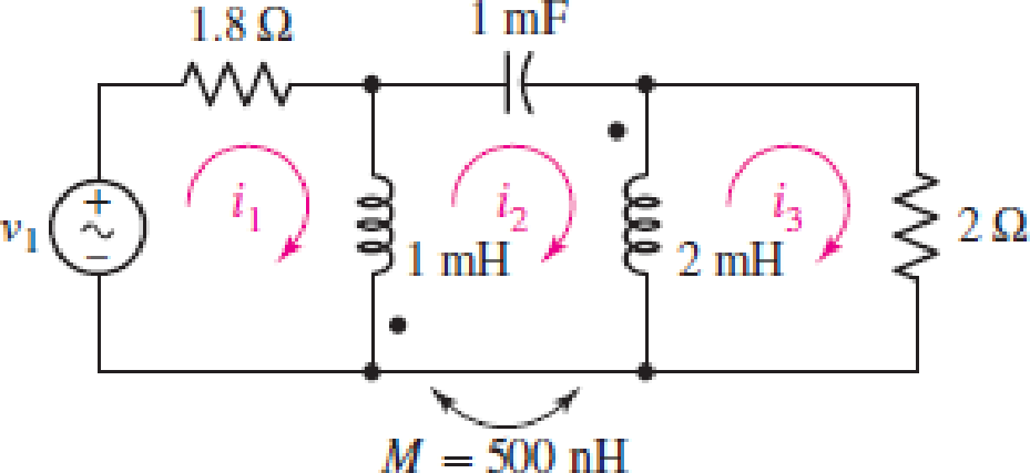
In the circuit of Fig. 13.43, M is reduced by an order of magnitude. Calculate i3 if v1 = 10 cos (800t − 20°) V.
FIGURE 13.43
Find the value of
Answer to Problem 15E
The value of
Explanation of Solution
Given data:
Refer to Figure 13.43 in the textbook for the given circuit.
The value of mutual inductance is reduced by an order of magnitude. Therefore, write the value of mutual inductance as follows:
Formula used:
Write the expression for reactance due to self-inductance as follows:
Here,
Write the expression for reactance due to capacitance as follows:
Here,
Write the expression for reactance due to mutual-inductance as follows:
Here,
Calculation:
From the given source voltage, write the value of angular frequency and the source voltage
Rewrite the expression for
Substitute
Substitute
Substitute
Substitute
Use the obtained values of reactance due to inductor and capacitors and draw the phasor representation for the given circuit as shown in Figure 1.
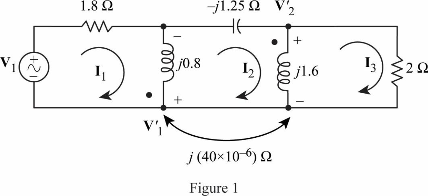
Apply KVL to the loop-
Neglect the dimensions and write the expression as follows:
Apply KVL to the loop-
Apply KVL to the loop-
Neglect the dimensions and write the expression as follows:
From the circuit in Figure 1, write the expression for
From the circuit in Figure 1, write the expression for
Rewrite the expression in Equation (4) as follows:
Substitute
Simplify the expression as follows:
Rearrange the expression in Equation (6) as follows:
Substitute
Simplify the expression as follows:
From Equation (9), substitute
Simplify the expression as follows:
Substitute
Simplify the expression as follows:
Rearrange the expression in Equation (5) as follows:
Substitute
From Equation (11), substitute
Simplify the expression as follows:
Substitute
Simplify the expression as follows;
Rewrite the expression in polar form to obtain the value of
Conclusion:
Thus, the value of
Want to see more full solutions like this?
Chapter 13 Solutions
Loose Leaf for Engineering Circuit Analysis Format: Loose-leaf


- Explore the challenges and benefits of implementing power electronics-based grid solutions like STATCOM (Static Synchronous Compensator) for voltage control and stability.arrow_forwardsingle coil 600 turns instrument transformer, operating in the step-down mode with a 40 percent tap, supplies a 5 kVA, 0.88 power factor inductive load. The input to the transformer is 3.3 kV, 50 Hz. Assume that leakage effects and minor losses in transformer are negligible. Determine the following : (0) Turn ratio; (ii) Load current(in Amp); (iii) Incoming line current(in Amp); (iv) Transformed current (in Amp); (v) Apparent power conducted(in kVA)and (vi) Apparent power transformed"arrow_forwardPlease Solve ASPS. A 100 kVA, 2000/400 V, 50 Hz, single phase shell type transformer has sandwitch coils. There are two full HIV coils, one full LV coil and two half LV colls. Calculate the value of leakage reactance referred to HV side if the other data given is, depth of HV coil = 4 cm depth of LV coil = 3.6 cm depth of duct between IIV and LV= 1.6 cm width of winding 12 cm length of mean turns = 150 cm HV winding turns = 200 Also calculate the per unit reactance.arrow_forward
- An Electrical engineer is asked by a client to prepare a technical specification on specific items connected with a project. Hence, the engineer is requested to prepare the technical specification of the following: PROJECT: A Subdivision Development Lot AREA; 2 Hectares LOCATION: Brgy. Kanlurang Mayao, Lucna City Technical specification of fuse cutout Technical specification of transformerarrow_forwardCalculate the energy stored in the coupled coils at t = 10 ms if M = 0.2 H and vs = 12 cos 10t V.arrow_forwardKindly answer A coil has an inductance of 40 mH and negligible resistance. Calculate its inductive reactance and the resulting current if connected to (a) a 240V, 50 Hz supply, and (b) a 100V, 1 kHz supplyarrow_forward
- Calculate the mesh currents in the circuit of Fig. 13.11.arrow_forwardQ13) An ideal transformer connected to a 240V mains, supplies a 12V, 150W lamp. Calculate the Transformer turns ratio. a. 45 b. 0.05 c. 50 d. 5arrow_forwardGiven a series circuit comprised of the following element: 53.06-ohm resistor, practical inductor with internal resistance of 0.52 ohm and reactance of 39.04 ohms; and a capacitor with reactance of 19.17 ohms. Compute for equivalent impedance angle in degrees. Note: No Scientific notation. Do not round off in the middle of calculation. Use stored values. Please round off to the nearest 4 decimal places for the final answer.arrow_forward
- Given a 115kV/13.2kV distribution transformer rated at 30MVA with an 8% nameplate impedance what is the full Load current in ampsarrow_forwardElectrical engineering A 375 kVA, 6600/400 V, 3-phase core type transformer has a total loss of 3700 watts on full load. The transformer tank is 1.25 m in height and 1 m × 0.5 m in plan. Design a suitable scheme for cooling tubes if the average temperature rise is to be limited to 35 °C. The diameter of the tube is 50 mm and are spaced 75 mm from each other. The average height of the tube is 1.05 m.arrow_forwardA coil of inductance 318.3 mH and negligible resistance is connected in series with a 200 ohm resistor to a 240V, 50 Hz supply. Calculate the inductive reactance of the coil, the impedance of the circuit, the current in the circuit, the p.d. across each component, and the circuit phase angle.arrow_forward
 Introductory Circuit Analysis (13th Edition)Electrical EngineeringISBN:9780133923605Author:Robert L. BoylestadPublisher:PEARSON
 Delmar's Standard Textbook Of ElectricityElectrical EngineeringISBN:9781337900348Author:Stephen L. HermanPublisher:Cengage Learning
 Programmable Logic ControllersElectrical EngineeringISBN:9780073373843Author:Frank D. PetruzellaPublisher:McGraw-Hill Education
 Fundamentals of Electric CircuitsElectrical EngineeringISBN:9780078028229Author:Charles K Alexander, Matthew SadikuPublisher:McGraw-Hill Education
 Electric Circuits. (11th Edition)Electrical EngineeringISBN:9780134746968Author:James W. Nilsson, Susan RiedelPublisher:PEARSON
 Engineering ElectromagneticsElectrical EngineeringISBN:9780078028151Author:Hayt, William H. (william Hart), Jr, BUCK, John A.Publisher:Mcgraw-hill Education,