
Concept explainers
Videos
Find the Thevenin equivalent to the left of the load Z in the circuit of Fig. 13.87.
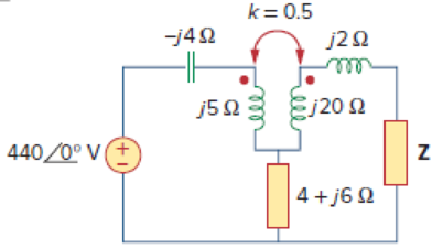
Calculate the Thevenin equivalent to the left side of load Z in the coupled coils circuit.
Answer to Problem 18P
The Thevenin equivalent circuit parameters are
Explanation of Solution
Given data:
Refer to Figure 13.87 in the textbook for the circuit with coupled coils.
Calculation:
To the Thevenin’s voltage, open-circuit the impedance Z. Then, the current
Modify the Figure 13.87 by convert the circuit into the frequency domain and convert the coupled inductors into their dependent source equivalent. The modified circuit as shown in Figure 1.

Apply Kirchhoff's voltage law to the loop 1 contains current
Substitute 0 for
Modify the Equation as follows.
Write the expression for the open-circuit voltage.
Substitute
Consider the expression for the Thevenin voltage.
Substitute
Modify the Figure 1 by short-circuiting the load side contains current
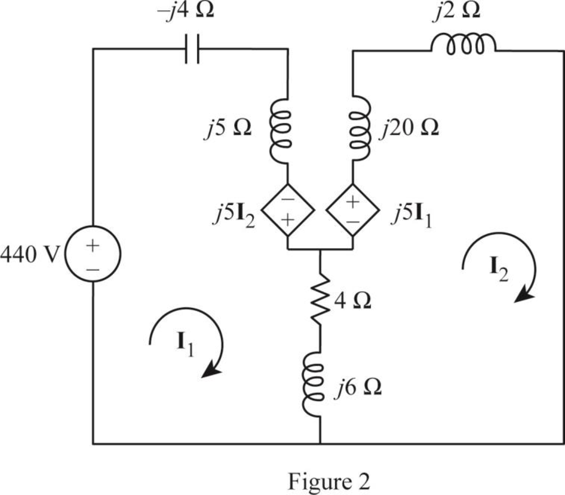
From Figure 2, consider that the loops 1 and 2 contain the currents
Apply Kirchhoff's voltage law to the loop 1 in Figure 1.
Apply Kirchhoff's voltage law to the loop 2 in Figure 1.
Write equations (1) and (2) in matrix form as follows.
Write the MATLAB code to solve the equation (3).
A = [(4+j*7) -(4+j*11);-(4+j*11) (4+j*28)];
B = [440; 0];
I = inv(A)*B
The output in command window:
I =
61.069 - 121.926i
14.369 - 54.571i
From the MATLAB output, the currents
And
The short-circuit current
Substitute
Write the expression for Thevenin’s equivalent impedance.
Substitute
Conclusion:
Thus, the Thevenin equivalent circuit parameters are
Want to see more full solutions like this?
Chapter 13 Solutions
Fundamentals of Electric Circuits


- A 2300/230 V distribution transformer is delivering a load of 50 kW to a certain part of a community. If the total wire impedance is .05 Ω, what power is actually dellvered? Ans. 47.64 kWarrow_forwardAn industrial plant is powered with a delta delta system, along with a transformer bank made up of single-phase transformers of 20KVA, 2300/230 V each. The bank supplies a 40 KVA load with a power factor of 0.7 (-). If a damaged transformer is removed for repair, calculate:a) The load in KVA that each transformer has.b) The nominal load of the transformer bank W.arrow_forwardA 5,000-kVA, 3-phase transformer, 13.2/33-kV, A/Y, has a copper loss of 11 kW. The impedance drop at full-load is 7.5%. Calculate the primary voltage when a load of 4000 kW at 0.8 p.f. is delivered at 33 kv.arrow_forward
- A 100kVA, 14/2.4kV, 60Hz single phase transformer is supplied through a line of 38+j140 ohm impedance. The transformer impedance referred to the secondary is 1+j4. A load of 90kW at 0.9 pf lagging is connected at the secondary terminal. Find the supply voltage (V1) if the load voltage is 2.3kV. Answer in whole number.arrow_forwardIn the ideal transformer circuit of Fig. 13.38, find and the complexpower supplied by the source.arrow_forwardA network is composed of the utility having Ssc=500MVA, and an 800KVA transformer, rated at 20KV/410V (no load), whose voltage impedance is 5%, and whose load losses are 5400watts. the short circuit at the secondary of the transformer using the impedance method is: Select one: 45.8KA None of these 21.83KA 30.5KAarrow_forward
- An Electrical engineer is asked by a client to prepare a technical specification on specific items connected with a project. Hence, the engineer is requested to prepare the technical specification of the following: PROJECT: A Subdivision Development Lot AREA; 2 Hectares LOCATION: Brgy. Kanlurang Mayao, Lucna City Technical specification of fuse cutout Technical specification of transformerarrow_forwardIn a 30kVA, 2000/220V power transformer, the iron and full load copper losses are 400W and 450W respectively. Calculate the efficiency at unity power factor in half load condition.arrow_forwardA network is composed of the utility having Ssc=500MVA, and an 800KVA transformer, rated at 20KV/410V (no load), whose voltage impedance is 5%, and whose load losses are 5400watts. the short circuit at the secondary of the transformer using the impedance method is: Select one: a)30.5KA b)None of these c)45.8KA d)21.83KAarrow_forward
- A 2,400/480-V rms step-down ideal transformer delivers 50 kW to a resistive load. Calculate:(a) the turns ratio(b) the primary current(c) the secondary currentarrow_forwardA 3 phase 150kVA, 4160V 0.80 lagging pf load is to be supplied by 3 single phase transformer having turns ratio of 2. Calculate the current that flows in the primary windings if the transformers are connected delta delta.arrow_forwardA 5KVA, 120/540V single phase transformer has a secondary terminal voltage of 500 V when loaded.Determine the regulation of the transformer.arrow_forward
 Introductory Circuit Analysis (13th Edition)Electrical EngineeringISBN:9780133923605Author:Robert L. BoylestadPublisher:PEARSON
 Delmar's Standard Textbook Of ElectricityElectrical EngineeringISBN:9781337900348Author:Stephen L. HermanPublisher:Cengage Learning
 Programmable Logic ControllersElectrical EngineeringISBN:9780073373843Author:Frank D. PetruzellaPublisher:McGraw-Hill Education
 Fundamentals of Electric CircuitsElectrical EngineeringISBN:9780078028229Author:Charles K Alexander, Matthew SadikuPublisher:McGraw-Hill Education
 Electric Circuits. (11th Edition)Electrical EngineeringISBN:9780134746968Author:James W. Nilsson, Susan RiedelPublisher:PEARSON
 Engineering ElectromagneticsElectrical EngineeringISBN:9780078028151Author:Hayt, William H. (william Hart), Jr, BUCK, John A.Publisher:Mcgraw-hill Education,