Concept explainers
Videos
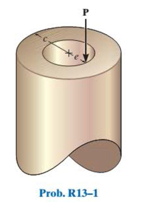
The post has a circular cross section of radius c. Determine the maximum radius e at which the load P can be applied so that no part of the post experiences a tensile stress. Neglect the weight of the post.
Find the maximum radius e at which the load P can be applied.
Answer to Problem 1RP
The maximum radius e at which the load P can be applied is
Explanation of Solution
Given information:
The post has a circular cross section of radius c.
Neglect the weight of the post.
Calculation:
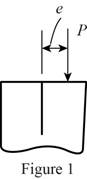
Sketch the Free Body Diagram of the applied load P as shown in Figure 1.
Apply the normal stress
Apply the stress formula as shown below.
Here, P is the applied load, A is the area of the cross section, M is the moment at the point, y is the centroid, and I is the moment of inertia.
Equate the Equation (1) and (2).
Determine the area of cross section as shown below.
Here, r is the radius of the cross section.
Substitute c for r .
Determine the moment of inertia as shown in below:
Substitute c for r .
Sketch the free body diagram of the moment at the point as shown in Figure 2.
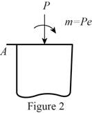
Refer to Figure 2.
Find the moment using the calculation.
Substitute
Therefore, the maximum radius e at which the load P can be applied is
Want to see more full solutions like this?
Chapter 13 Solutions
Statics And Mechanics Of Materials, Student Value Edition Plus Mastering Engineering With Pearson Etext -- Access Card Package (5th Edition)
Additional Engineering Textbook Solutions
Thermodynamics: An Engineering Approach
Fundamentals of Heat and Mass Transfer
Fluid Mechanics: Fundamentals and Applications
Applied Fluid Mechanics (7th Edition)
Engineering Mechanics: Statics & Dynamics (14th Edition)


- The three steel wires are used to support the load. If the wires have an allowable tensile stress of σallow = 165 MPa, and wire AB has a diameter of 5 mm, wire BD has a diameter of 7 mm and wire BC has a diameter of 6 mm. Determine the maximum force P that can be applied before one of the wires fails.arrow_forwardThe supporting wheel on a scaffold is held in place on the leg using a 4-mm-diameter pin. If the wheel is subjected to a normal force of 3 kN, determine the average shear stress in the pin. Assume the pin only supports the vertical 3-kN load.arrow_forwardThe thin-walled cylinder can be supported in one of two ways as shown. Determine the state of stress in the wall of the cylinder for both cases if the piston P causes the internal pressure to be 65 psi. The wall has a thickness of 0.25 in. and the inner diameter of the cylinder is 8 in.arrow_forward
- Rods AB and BC each have a diameter of 5mm. If the load of P= 2kN is applied to the ring, determine the average normal stress in each rod of Ɵ - 60°arrow_forwardA thin hollow spherical container has a diameter 1 m and a thickness of 4 mm is subjected to an internal pressure. Determine the internal pressure the tensile stress of the element in the sphere is 500 kPa.arrow_forwardDetermine the maximum axial force P that can be applied to the bar. The bar is made from steel and has an allowable stress of σallow = 147 MPa.arrow_forward
- Determine the tensile stress developed in member AB due to a load of P = 500# at D. The member AB is thick and 2” widearrow_forwardA bar having a square cross section of 30 mm by 30 mm is 2 m long and is held upward. If it has a mass of 5 kg/m, determine the largest angle u, measured from the vertical, at which it can be supported before it is subjected to a tensile stress along its axis near the grip.arrow_forwardThe frame supports the distributed load shown. Determine the state of stress acting at point D. Show the results on a differential element at this point.arrow_forward
- Determine the shortest distance d to the edge of the plate at which the force P can be applied so that it produces no compressive stresses in the plate at section a–a. The plate has a thickness of 10 mm and P acts along the centerline of this thickness.arrow_forwardThe pier is made of a material having a specific weight g. If it has a square cross-section, determine its width w as a function of z so that the average normal stress in the pier remains constant. The pier supports a constant load P at its top where its width is w1.arrow_forwardThe two aluminum rods AB and AC have diameters of 10 mm and 8 mm, respectively. Determine the largest vertical force P that can be supported. The allowable tensile stress for the aluminum is sallow = 150 MPa.arrow_forward
 Elements Of ElectromagneticsMechanical EngineeringISBN:9780190698614Author:Sadiku, Matthew N. O.Publisher:Oxford University Press
 Mechanics of Materials (10th Edition)Mechanical EngineeringISBN:9780134319650Author:Russell C. HibbelerPublisher:PEARSON
 Thermodynamics: An Engineering ApproachMechanical EngineeringISBN:9781259822674Author:Yunus A. Cengel Dr., Michael A. BolesPublisher:McGraw-Hill Education
 Control Systems EngineeringMechanical EngineeringISBN:9781118170519Author:Norman S. NisePublisher:WILEY
 Mechanics of Materials (MindTap Course List)Mechanical EngineeringISBN:9781337093347Author:Barry J. Goodno, James M. GerePublisher:Cengage Learning
 Engineering Mechanics: StaticsMechanical EngineeringISBN:9781118807330Author:James L. Meriam, L. G. Kraige, J. N. BoltonPublisher:WILEY