
Concept explainers
Videos
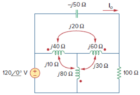
Find current Io in the circuit of Fig. 13.91.
Calculate the current
Answer to Problem 22P
The current
Explanation of Solution
Given data:
Refer to Figure 13.91 in the textbook for the coupled coil circuit.
Calculation:
In Figure 13.91, replace the coupled inductor by dependent source model by using Figure 13.8. The modified circuit as shown in Figure 1.
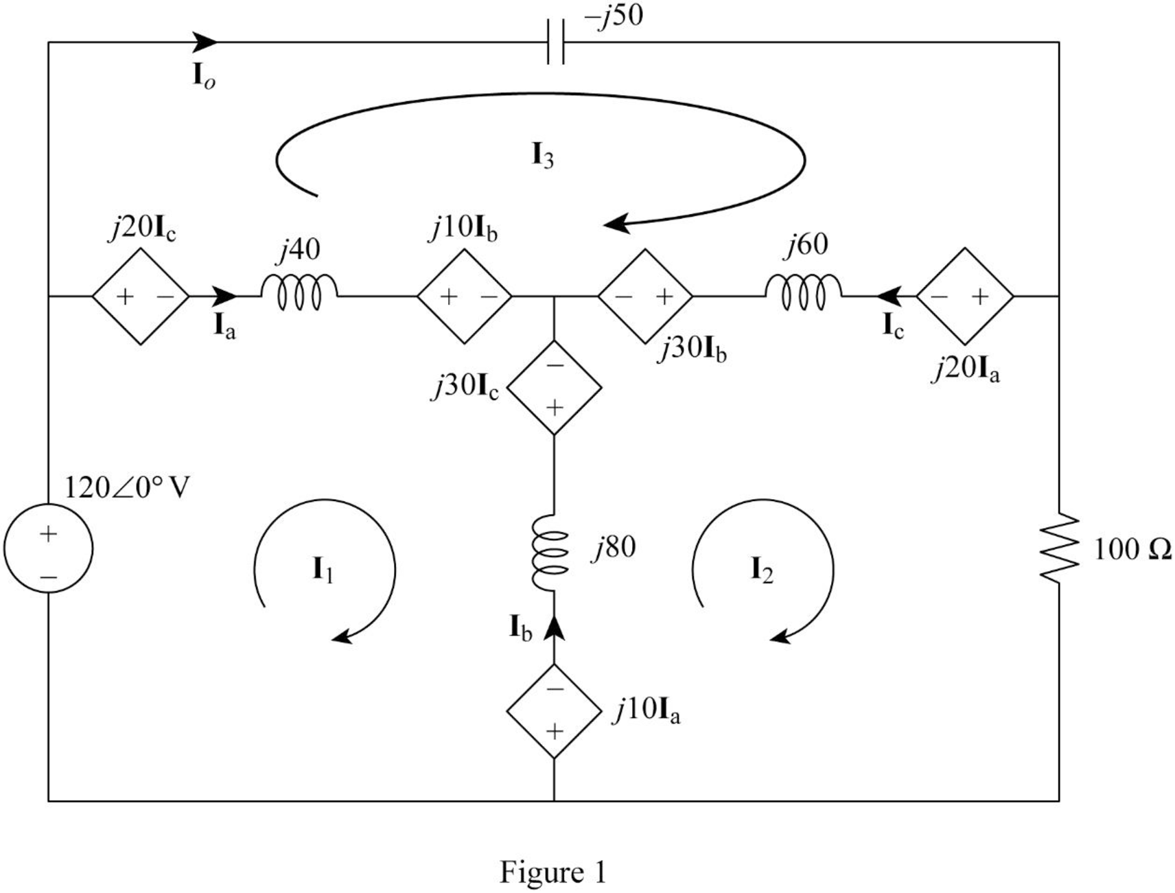
In Figure 1, consider the followings.
From Figure 1, consider that the loops 1, 2 and 3 contain the currents
Apply Kirchhoff's voltage law to the loop 1 in Figure 1.
Apply Kirchhoff's voltage law to the loop 2 in Figure 1.
Apply Kirchhoff's voltage law to the loop 3 in Figure 1.
Write equations (1), (2), and (3) in matrix form as follows.
Write the MATLAB code to solve the equation (4).
A = [j*100 j*(-60) j*(-40); j*(-60) (100+j*80) j*(-20); j*(-40) j*(-20) j*10];
B = [120; 0; 0];
C = inv(A)*B
The output in command window:
C =
0.45231 + 0.34154i
-0.19385 + 0.71077i
1.42154 + 2.78769i
From the MATLAB output, the currents
And
Write the expression for the current
Substitute
Conclusion:
Thus, the current
Want to see more full solutions like this?
Chapter 13 Solutions
Fundamentals of Electric Circuits


- What is the impedance of a transformer coil that has 340' of #18 copper wire and an inductance of 70mH at 60Hz? 1000’ of #18 copper wire is 16 ohms.arrow_forwardCalculate the mesh currents in the circuit of Fig. 13.11.arrow_forwardKindly answer A coil has an inductance of 40 mH and negligible resistance. Calculate its inductive reactance and the resulting current if connected to (a) a 240V, 50 Hz supply, and (b) a 100V, 1 kHz supplyarrow_forward
- A resistor of 6 ohms and an unknown impedance coil in series draws 12 A from a 120 V, 60 Hz line. If the real power taken from the line is 1152 Watts, what is the coil inductance?arrow_forwardA transformer connected to a120 V (rms) ac line is to supply 12.0 V (rms) to a portable electronic device.The load resistance in the secondary is 5.00 Ω. What rms current must the secondary supply?arrow_forwardCalculate the reactance of a coil of inductance 0.2H when it is connected to a 50Hz supply. A. 62.83ohms B. 63.82ohms C. 62.38ohms D. 63.28ohmsarrow_forward
- Calculate the energy stored in the coupled coils at t = 10 ms if M = 0.2 H and vs = 12 cos 10t V.arrow_forwardCalculate:Reactive, apparent and active power of the circuit, consider the power supply 120V rms and a frequency of 60 Hz.arrow_forwardThe voltage v = 207 sin(100t+50°) V is connected acroos a 5-H inductor. Determine the inductive reactance. Write the magnitude only in four decimal places.arrow_forward
- When the waveform shown in fig. (1) is applied to true responding ac voltmeter, the output would be (5.314 V). If the same signal is applied to average responding ac voltmeter, what will be: 1. The indicate value. 2. The true value. 3. The true form factor. 4. The indicate crest factor.arrow_forwardThree similar coils ,connected in star,take a total power of 1.5 kW at p.f. of 0.2 lagging from a 3-0hase ,400V.50Hz supply .calculate the resistance and inductance of each coilarrow_forwardA coil of inductance 318.3 mH and negligible resistance is connected in series with a 200 resistor to a 240V, 50 Hz supply. Calculate (a) the inductive reactance of the coil, (b) the impedance of the circuit, (c) the current in the circuit, (d) the p.d. across each component, and (e) the circuit phase anglearrow_forward
 Introductory Circuit Analysis (13th Edition)Electrical EngineeringISBN:9780133923605Author:Robert L. BoylestadPublisher:PEARSON
 Delmar's Standard Textbook Of ElectricityElectrical EngineeringISBN:9781337900348Author:Stephen L. HermanPublisher:Cengage Learning
 Programmable Logic ControllersElectrical EngineeringISBN:9780073373843Author:Frank D. PetruzellaPublisher:McGraw-Hill Education
 Fundamentals of Electric CircuitsElectrical EngineeringISBN:9780078028229Author:Charles K Alexander, Matthew SadikuPublisher:McGraw-Hill Education
 Electric Circuits. (11th Edition)Electrical EngineeringISBN:9780134746968Author:James W. Nilsson, Susan RiedelPublisher:PEARSON
 Engineering ElectromagneticsElectrical EngineeringISBN:9780078028151Author:Hayt, William H. (william Hart), Jr, BUCK, John A.Publisher:Mcgraw-hill Education,