
Concept explainers
Calculate the impedance
Answer to Problem 25P
The impedance
Explanation of Solution
Given data:
Refer to Figure 13.94 in the textbook for the circuit with coupled coils.
The coupling co-efficient is 0.5.
Calculation:
Consider the expression for the mutual inductance.
Substitute 0.5 for k, 1 H for
From Figure 13.94, the value of
Consider the expression for the inductive reactance.
Substitute 1 H for L and
Substitute 2 H for L and
Consider the expression for the capacitive reactance.
Substitute 0.5 F for C and
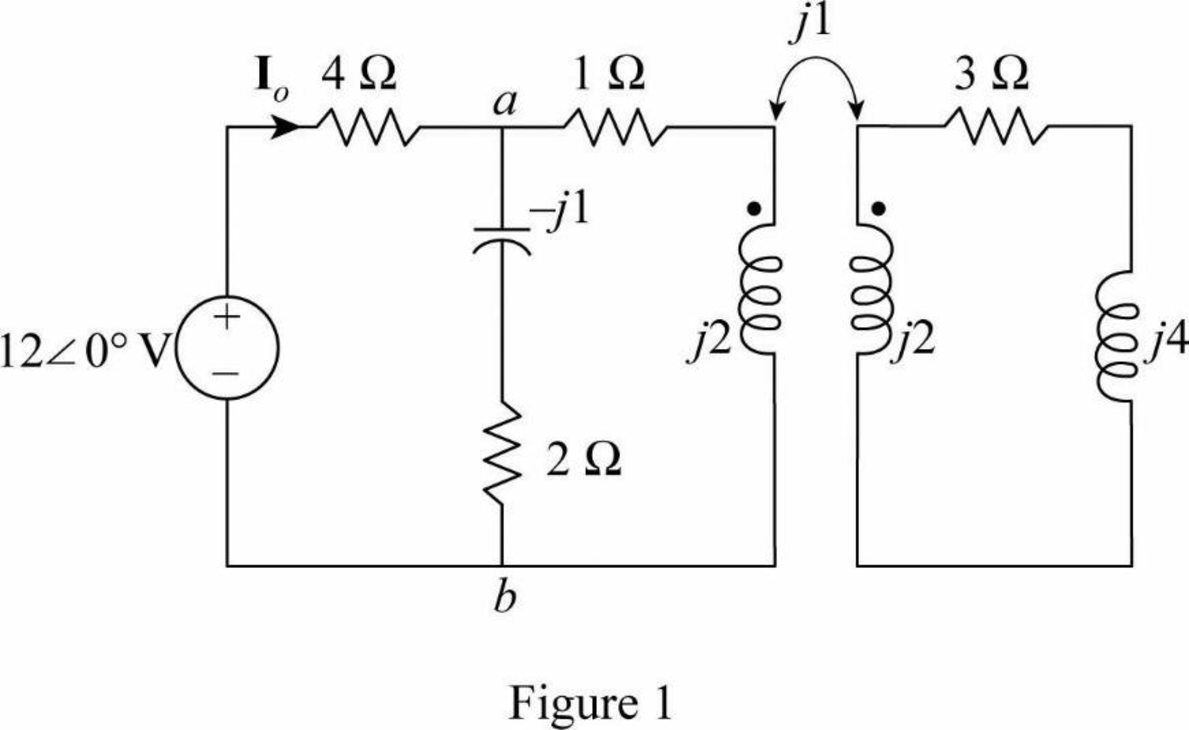
Modify the Figure 13.94 by transforming the time-domain circuit with coupled-coils to frequency domain of the circuit with coupled-coil. The frequency domain equivalent circuit is shown in Figure 1.
Write the expression for the impedance
Consider the expression for the reflected impedance
Substitute 2 for
Substitute
Simplify the Equation as follows.
Write the expression for the current
Substitute
The value of current
Convert the current from polar form to time domain form.
MATLAB code:
The MATLAB code using equations (3), (4) and (5) is,
M=0.5;
R2=3;
w=2;
L2=1;
ZL=4*j;
ZR=(w^2 * M^2)/(R2 + j*w*L2 + ZL);
Zab= (2-1*j)*(1+2*j+ZR)/(2-j+1+2*j+ZR)
Io=12/(Zab+4)
Then the MATLAB output is,
Zab = 1.4354 + 0.4639i
Io = 2.1918 - 0.1871i
Form the MATLAB output, impedance
Form the MATLAB output, current
The output is satisfied with analytical solution.
Conclusion:
Thus, the impedance
Want to see more full solutions like this?
Chapter 13 Solutions
Fundamentals of Electric Circuits


- The impedance coil absorbs 250 watts when connected across 220 V, 60 Hz mains, it is then connected across 110 V, 25 Hz mains and also absorbs 250 watts. What is the inductance of the coil? Show complete solution.arrow_forwardA 2300/230 V distribution transformer is delivering a load of 50 kW to a certain part of a community. If the total wire impedance is .05 Ω, what power is actually dellvered? Ans. 47.64 kWarrow_forwardWhat will be the value of coupling factor between two coils, when the self inductnce of each coil is 30 mH and the mutual Inductance between them is 60 mH ?arrow_forward
- i. Three identical coils connected in star, take a total power of 1.5 kW at a pf of 0.2 lagging from a 3-phase 400-V, 60 Hz line. Find the inductance of each coil.arrow_forwardA 3-Φ, 5 KW induction motor has a p.f of 0.75 lagging. A bank of capacitors is connected in delta across the supply terminals and p.f raised to 0.9 lagging. Determine the KVAR rating of the capacitor connected in each phase. Also comment on the type of supplied KVAR, Whether it is unity, leading or lagging.arrow_forwardAn ac motor is connected to a 560v, 60hz line. The motor has a current draw at full load of 53A. A wattmeter indicates a true power of 18 700 W. Find the power factor of the motor and the amount of capacitance that should be connected in parallel with the motor to correct the power factor to 100% or unity.arrow_forward
- A coil with an inductance of 100 mH is connected in series with a resistance of 20 Ω. To this system If 110 V AC with a frequency of 25 Hz is applied, the impedance, current, resistance and coil of the system Find the voltage at the terminals, active, reactive and apparent power values of the system.arrow_forwardFind the kVAR rating and capacitance required to improve the power factor to 0.96 (lagging)arrow_forwardA relay coil is connected to a 210V, 50Hz supply. If it has a resistance of 30Ω and an inductance of 0.5H, calculate thea pparent power and the power factor.arrow_forward
- Calculate the equivalent impedance of a circuit in which a coil of wire having a value of 5∠53.2ºohm is connected in parallel with a capacitive reactance of 6.25 ohms.arrow_forwardA choking coil having a resistance of 20 Ω and an inductance of 0.07 henry is connected with a capacitor of 60 μF capacitance which is in series with a resistor of 50 Ω. Calculate the total current and the phase angle when this arrangement is connected to 200-V, 50 Hz mains.arrow_forwardCalculate the equivalent impedance of a circuit where a coil of (5H, angle 53.2 Deg.) ohms is connected in parallel with a capacitive reactance of 6.25 ohms.arrow_forward
 Introductory Circuit Analysis (13th Edition)Electrical EngineeringISBN:9780133923605Author:Robert L. BoylestadPublisher:PEARSON
 Delmar's Standard Textbook Of ElectricityElectrical EngineeringISBN:9781337900348Author:Stephen L. HermanPublisher:Cengage Learning
 Programmable Logic ControllersElectrical EngineeringISBN:9780073373843Author:Frank D. PetruzellaPublisher:McGraw-Hill Education
 Fundamentals of Electric CircuitsElectrical EngineeringISBN:9780078028229Author:Charles K Alexander, Matthew SadikuPublisher:McGraw-Hill Education
 Electric Circuits. (11th Edition)Electrical EngineeringISBN:9780134746968Author:James W. Nilsson, Susan RiedelPublisher:PEARSON
 Engineering ElectromagneticsElectrical EngineeringISBN:9780078028151Author:Hayt, William H. (william Hart), Jr, BUCK, John A.Publisher:Mcgraw-hill Education,