
Concept explainers
Calculate the support reactions for the given structure using method of consistent deformation.
Sketch the shear and bending moment diagrams for the given structure.
Answer to Problem 42P
The horizontal reaction at D is
The vertical reaction at D is
The horizontal reaction at A is
The vertical reaction at A is
The moment at A is
Explanation of Solution
Given information:
The structure is given in the Figure.
Apply the sign conventions for calculating reactions, forces and moments using the three equations of equilibrium as shown below.
- For summation of forces along x-direction is equal to zero
- For summation of forces along y-direction is equal to zero
- For summation of moment about a point is equal to zero
- Consider the positive sign indicates the clockwise moment the negative sign indicates the counterclockwise moment.
Calculation:
Find the degree of indeterminacy of the structure:
Degree of determinacy of the frame is equal to the number of unknown reactions minus the number of equilibrium equations.
The frame is supported by 5 support reactions and the number of equilibrium equations is 3.
Therefore, the degree of indeterminacy of the frame is
Select the vertical reaction
Release the support D and consider the notation of moments due to external load as
Sketch the free body diagram of primary frame subjected to external loading without support D as shown in Figure 1.
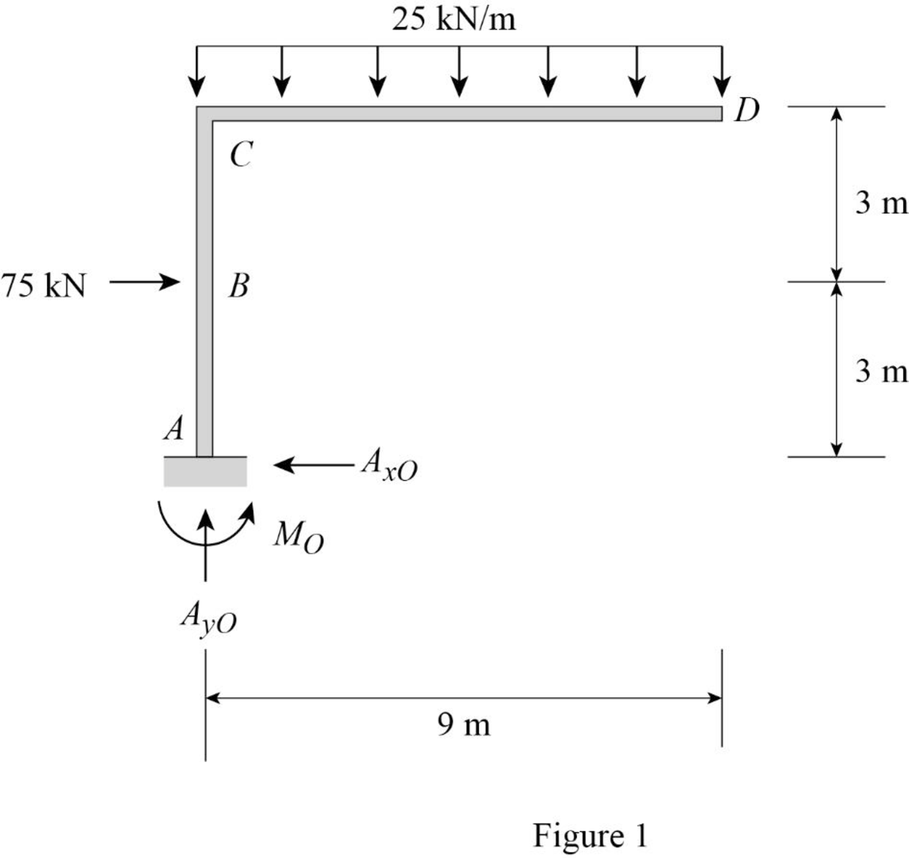
Find the reactions at the supports without considering support D using equilibrium equations:
Summation of moments of all forces about A is equal to 0.
Summation of forces along y-direction is equal to 0.
Summation of forces along x-direction is equal to 0.
For unit value of the unknown redundant
Consider the notation of moments due to external load as
Sketch the free body diagram of primary frame Subjected to unit value of redundant
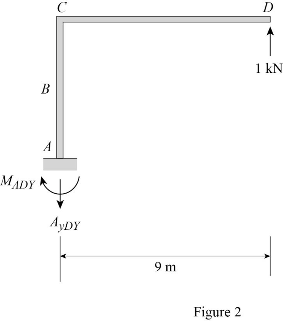
Find the support reaction and moment at A when 1 kN vertical load applied at D.
Summation of moments of all forces about A is equal to 0.
Summation of forces along y-direction is equal to 0.
Summation of forces along x-direction is equal to 0.
For unit value of the unknown redundant
Consider the notation of moments due to external load as
Sketch the free body diagram of primary frame Subjected to unit value of redundant
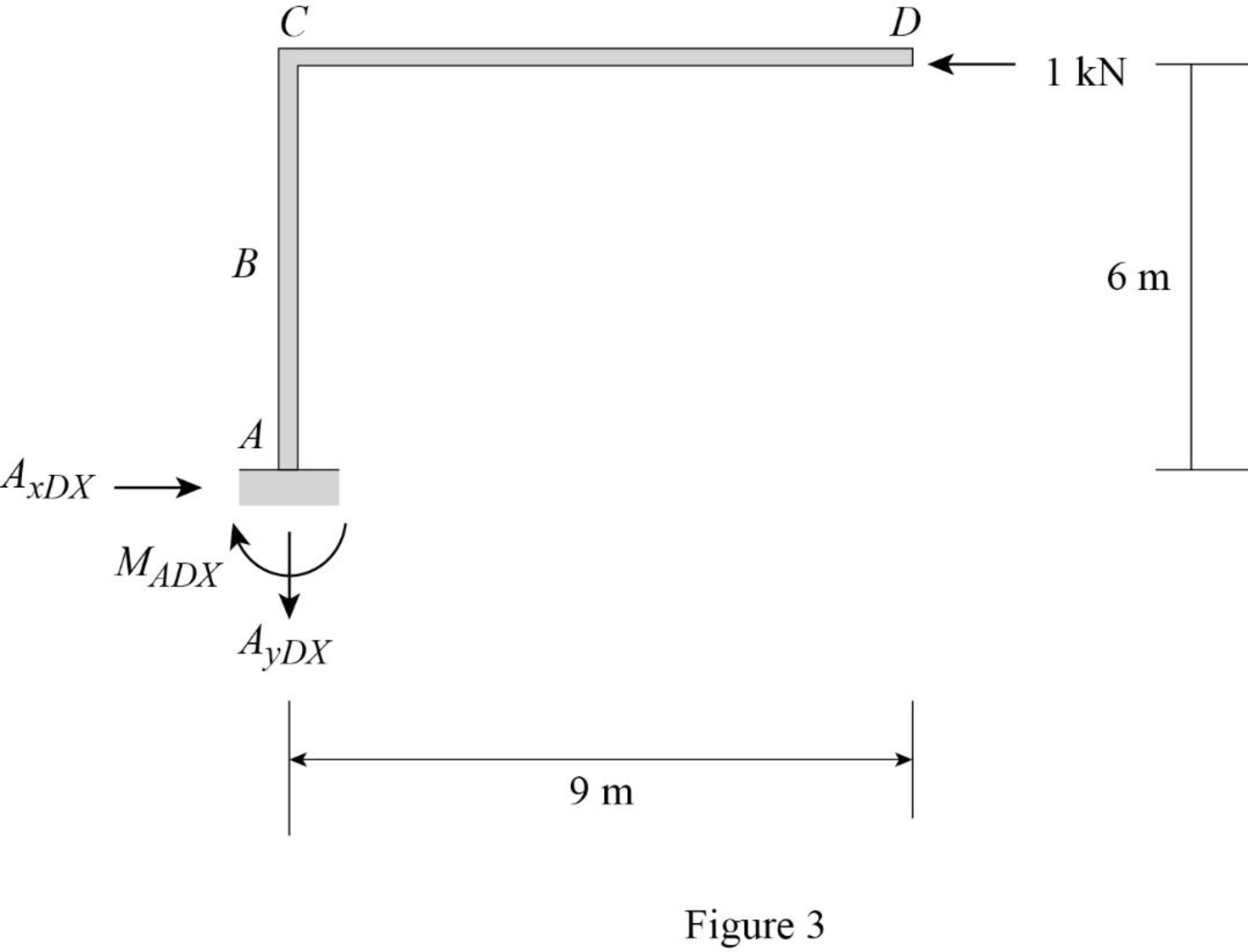
Find the support reaction and moment at A when 1 kN horizontal load applied at D.
Summation of moments of all forces about A is equal to 0.
Summation of forces along y-direction is equal to 0.
Summation of forces along x-direction is equal to 0.
Find the moment equation of the frame for different sections on the frame.
Consider a section XX in the portion AB of the primary structure at a distance of x from A.
Refer Figure 1.
Draw the primary structure with section XX as shown in Figure 4.
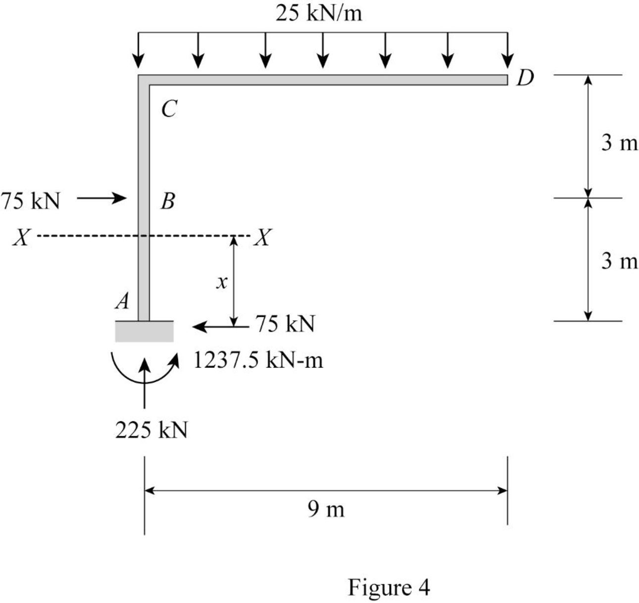
Refer Figure 4.
Consider origin as A.
Find the moment at section XX in the portion AB as shown in Figure 4.
Similarly calculate the moment of the remaining section in the external loading and redundant loading structures.
Tabulate the moment equation of different segment of frame as in Table 1.
| Segment | x-coordinate | ||||
| Origin | Limits (m) | ||||
| AB | A | 9 | |||
| BC | A | 9 | |||
| DC | D | 0 | |||
Let the horizontal deflection at point D due to external loading is
Calculate the value of
Calculate the value of
Calculate the value of
Calculate the value of
Calculate the value of
Find the reactions and moment for the given frame:
Find the horizontal and vertical reaction at D.
Show the first compatibility Equation as follows:
Substitute
Show the second compatibility Equation as follows:
Substitute
Solve Equation (1) and (2).
Therefore, the horizontal reaction at D is
Therefore, the vertical reaction at D is
Find the horizontal reaction at A.
Summation of forces along x-direction is equal to 0.
Therefore, horizontal reaction at A is
Find the vertical reaction at A.
Summation of forces along y-direction is equal to 0.
Therefore, the vertical reaction at A is
Find the moment at A.
Summation of moments of all forces about A is equal to 0.
Therefore, the moment at A is
Sketch the reactions and moment for the given frame as shown in Figure 5.
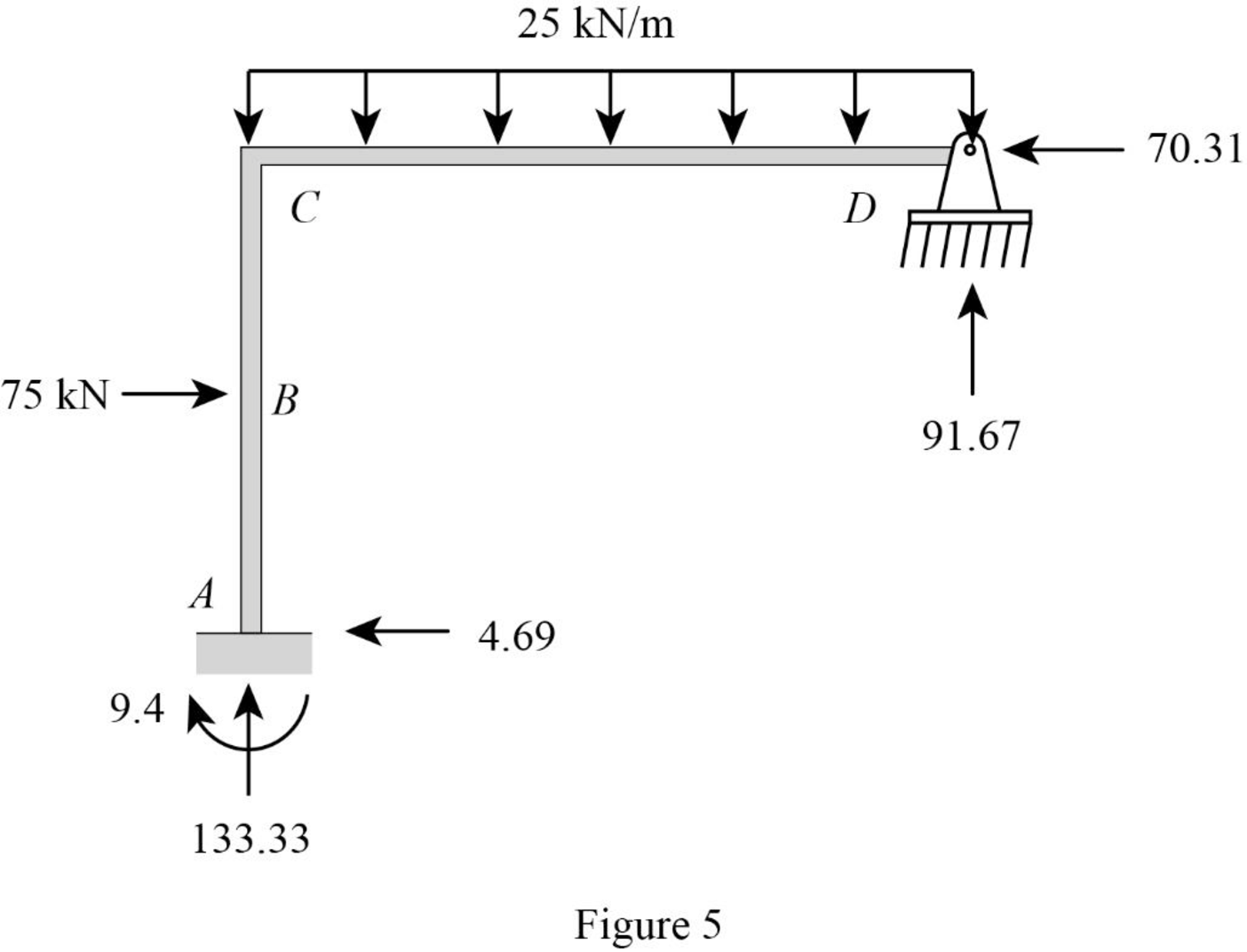
Find the shear force
For span AB,
At point A.
At point B, (positive side).
For span BC,
At point B, (negative side).
At point C,
For span CD,
At point C,
At point D,
Sketch the shear diagram for the given frame as shown in Figure 6.
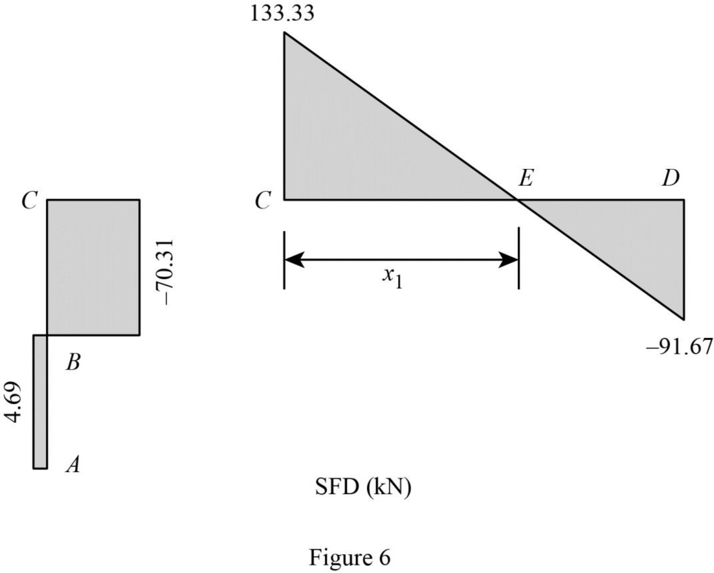
Find the bending moment
For span AB,
At point A,
At point B,
For span BC,
At point C,
For span CD,
At point C,
Find the point of zero force.
Take shear force at E.
Find the moment at E.
Find the moment at D.
At the hinged support, the moment is zero.
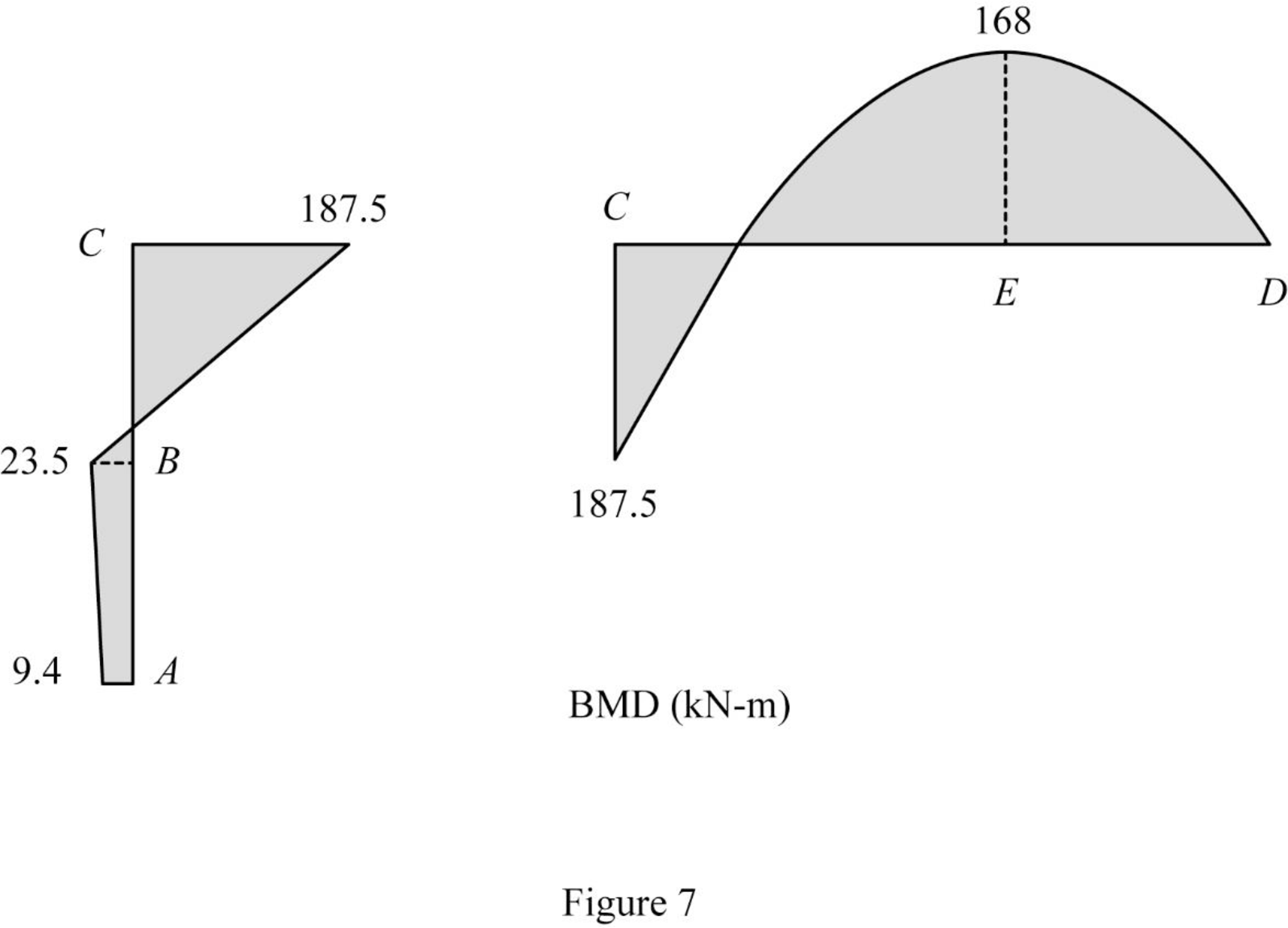
Sketch the bending moment diagram for the given frame as shown in Figure 7.
Want to see more full solutions like this?
Chapter 13 Solutions
Structural Analysis

