Given information:
The settlement at A (ΔA) is 10 mm=0.01 m.
The settlement at C (ΔC) is 65 mm=0.065 m.
The settlement at E (ΔE) is 40 mm=0.04 m.
The settlement at G (ΔG) is 25 mm=0.025 m.
The moment of inertia (I) is 500×106 mm4.
The modulus of elasticity (E) is 200 GPa.
The structure is given in the Figure.
Apply the sign conventions for calculating reactions, forces and moments using the three equations of equilibrium as shown below.
- For summation of forces along x-direction is equal to zero (∑Fx=0), consider the forces acting towards right side as positive (→+) and the forces acting towards left side as negative (←−).
- For summation of forces along y-direction is equal to zero (∑Fy=0), consider the upward force as positive (↑+) and the downward force as negative (↓−).
- For summation of moment about a point is equal to zero (∑Mat a point=0), consider the clockwise moment as negative and the counter clockwise moment as positive.
Calculation:
Sketch the free body diagram of the structure as shown in Figure 1.
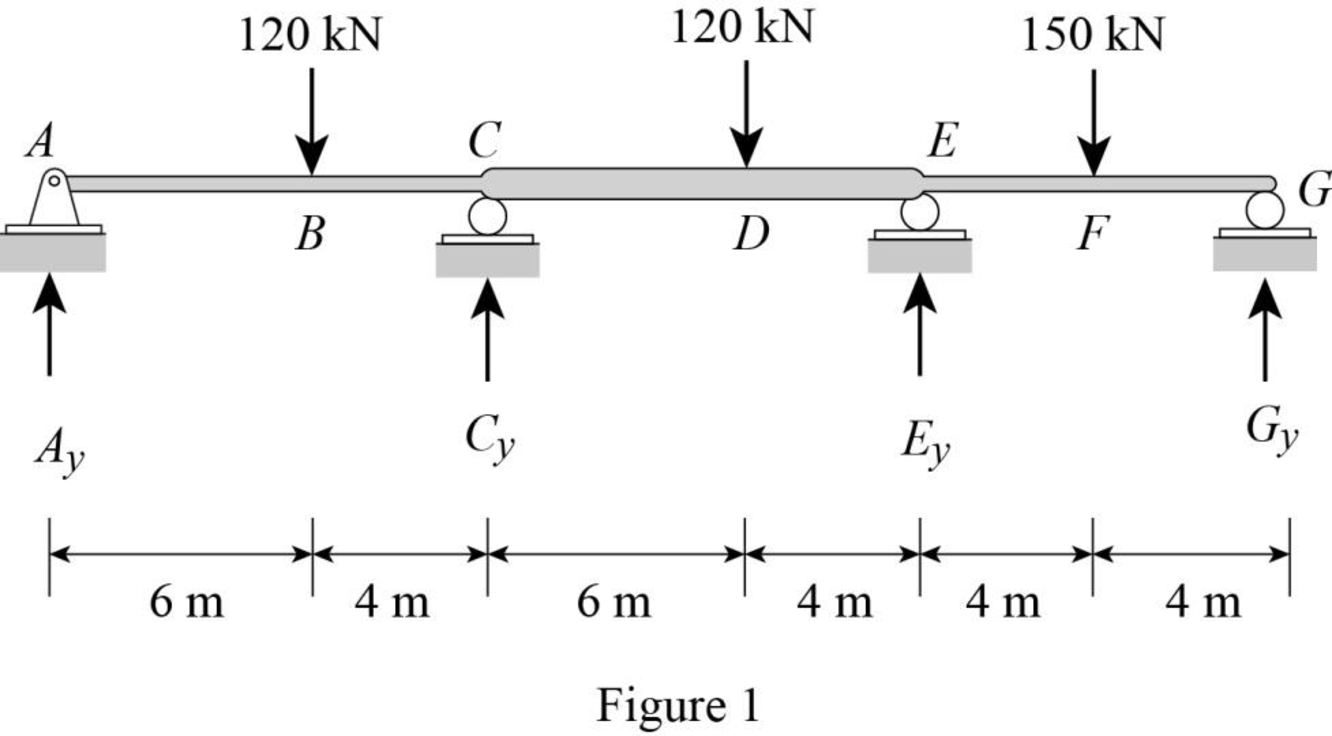
Calculate the degree of indeterminacy of the structure:
Degree of determinacy of the beam is equal to the number of unknown reactions minus the number of equilibrium equations.
The beam is supported by 5 support reactions and the number of equilibrium equations is 3.
Therefore, the degree of indeterminacy of the beam is i=2.
Select the bending moments at the supports E and C as redundant.
Let θCL and θCR are the slopes at the ends C of the left and right spans of the primary beam due to external loading.
Let θEL and θER are the slopes at the ends E of the left and right spans of the primary beam due to external loading.
Let fCCL and fCCR are the flexibility coefficient representing the slopes at C of the left and right spans due to unit value of redundant MC.
Let fEEL and fEER are the flexibility coefficient representing the slopes at E of the left and right spans due to unit value of redundant ME.
Let fCE be the flexibility coefficient representing the slope at point C of the primary beam due to unit value at point E.
Use beam deflection formulas:
Calculate the value of θCL using the relation:
θCL=Pa(L2−a2)6EIL
Substitute 120 kN for P, 6 m for a, and 10 m for L.
θCL=120×6(102−62)6EI(10)=768 kN⋅m2EI
Substitute 500×106 mm4 for E and 200 GPa for E.
θCL=768 kN⋅m2200 GPa×106 kN/m21 GPa×500×106 mm4×(1 m1,000 mm)4=0.00768 rad
Calculate the value of θCR using the relation:
θCR=Pb(L2−b2)6EIL
Substitute 120 kN for P, 4 m for b, 2I for I, and 10 m for L.
θCR=120×4(102−42)6E(2I)(10)=336 kN⋅m2EI
Substitute 500×106 mm4 for E and 200 GPa for E.
θCR=336 kN⋅m2200 GPa×106 kN/m21 GPa×500×106 mm4×(1 m1,000 mm)4=0.00336 rad
Calculate the value of θEL using the relation:
θEL=Pa(L2−a2)6EIL
Substitute 120 kN for P, 6 m for a, 2I for I, and 10 m for L.
θEL=120×6(102−62)6E(2I)(10)=384 kN⋅m2EI
Substitute 500×106 mm4 for E and 200 GPa for E.
θEL=384 kN⋅m2200 GPa×106 kN/m21 GPa×500×106 mm4×(1 m1,000 mm)4=0.00384 rad
Calculate the value of θER using the relation:
θER=PL216EI
Substitute 150 kN for P and 8 m for L.
θER=150(8)216EI=600 kN⋅m2EI
Substitute 500×106 mm4 for E and 200 GPa for E.
θER=600 kN⋅m2200 GPa×106 kN/m21 GPa×500×106 mm4×(1 m1,000 mm)4=0.006 rad
Calculate the value of fCCL using the relation:
fCCL=ML3EI
Substitute 1 kN⋅m for M and 10 m for L.
fCCL=1(10)3EI=10 kN⋅m2/kN⋅m3EI
Substitute 500×106 mm4 for E and 200 GPa for E.
fCCL=10 kN⋅m2/kN⋅m3×200 GPa×106 kN/m21 GPa×500×106 mm4×(1 m1,000 mm)4=0.0000333 rad/kN⋅m
Calculate the value of fCCR using the relation:
fCCR=ML6EI
Substitute 1 kN⋅m for M and 10 m for L.
fCCL=1(10)6EI=10 kN⋅m2/kN⋅m6EI
Substitute 500×106 mm4 for E and 200 GPa for E.
fCCL=10 kN⋅m2/kN⋅m6×200 GPa×106 kN/m21 GPa×500×106 mm4×(1 m1,000 mm)4=0.0000167 rad/kN⋅m
Calculate the value of fCE and fEC using the relation:
fCE=fEC=ML6EI
Substitute 1 kN⋅m for M, 2I for I, and 10 m for L.
fCE=fEC=1(10)6E(2I)=10 kN⋅m2/kN⋅m12EI
Substitute 500×106 mm4 for E and 200 GPa for E.
fCE=fEC=10 kN⋅m2/kN⋅m12×200 GPa×106 kN/m21 GPa×500×106 mm4×(1 m1,000 mm)4=0.00000833 rad/kN⋅m
Calculate the value of fEEL using the relation:
fEEL=ML6EI
Substitute 1 kN⋅m for M and 10 m for L.
fEEL=1(10)6EI=10 kN⋅m2/kN⋅m6EI
Substitute 500×106 mm4 for E and 200 GPa for E.
fEEL=10 kN⋅m2/kN⋅m6×200 GPa×106 kN/m21 GPa×500×106 mm4×(1 m1,000 mm)4=0.0000166 rad/kN⋅m
Calculate the value of fEER using the relation:
fEER=ML3EI
Substitute 1 kN⋅m for M and 8 m for L.
fEER=1(8)3EI=8 kN⋅m2/kN⋅m3EI
Substitute 500×106 mm4 for E and 200 GPa for E.
fEER=8 kN⋅m2/kN⋅m3×200 GPa×106 kN/m21 GPa×500×106 mm4×(1 m1,000 mm)4=0.0000267 rad/kN⋅m
The change of slope between the two tangents due to external load (θCO rel.) is expressed as,
θCO rel.=θCL+θCR=0.00768+0.00336=0.01104 rad
Similarly Calculate the value of θEO rel. as follows:
θEO rel.=θEL+θER=0.00384+0.006=0.00984 rad
The flexibility coefficient is expressed as fCC rel.=fCCL+fCCR.
fCC rel.=0.0000333+0.0000167=0.00005 rad/kN⋅m
Calculate the value of fEE rel. as follows:
fEE rel.=fEEL+fEER=0.0000166+0.0000267=0.0000433 rad/kN⋅m
Sketch the settlement at supports as shown in Figure 2.
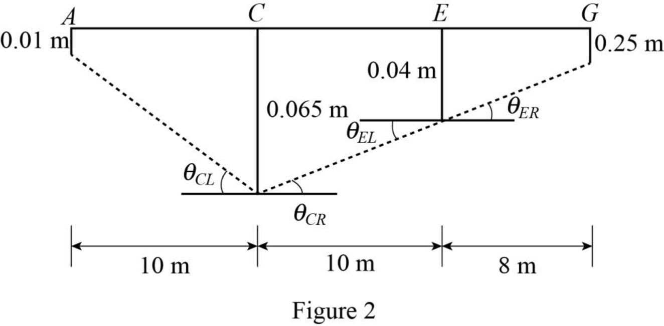
Refer to Figure 2.
Calculate the value θCL as shown below.
θCL=0.065−0.0110=0.0055 rad
Calculate the value θCR as shown below.
θCR=0.065−0.0410=0.0025 rad
Calculate the value θC as shown below.
θC=θCR+θCL=0.0025+0.0055=0.008 rad
Calculate the value θEL as shown below.
θEL=0.04−0.06510=−0.0025 rad
Calculate the value θER as shown below.
θER=0.04−0.0258=0.001875 rad
Calculate the value θC as shown below.
θE=θER+θEL=0.001875−0.0025=−0.000625 rad
Calculate the reactions for the given beam:
Show the compatibility Equations of the given beam as follows:
θCO rel.+fCC rel.MC+fCEME=θCθEO rel.+fECMC+fEE rel.ME=θE
Substitute 0.001104 rad for θCO rel., 0.00005 rad/kN⋅m for fCC rel., 0.00000833 rad/kN⋅m for fCE, 0.008 rad for θC, 0.00984 rad for θEO rel., 0.00000833 rad/kN⋅m for fEC, 0.0000433 rad/kN⋅m for fEE rel., and −0.000625 rad for θE.
0.001,104+0.00005MC+0.00000833ME=0.0081,104+5MC+0.833ME=8005MC+0.833ME=−304 (1)
0.00984+0.00000833MC+0.0000433ME=−0.000625984+0.833MC+4.33ME=−62.50.833MC+4.33ME=−1,046.5 (2)
Solve Equation (1) and Equation (2).
MC=−21.22 kN⋅mME=−237.6 kN⋅m
Sketch the span end moments and shears for span ABC, CDE, and EFG as shown in Figure 3.
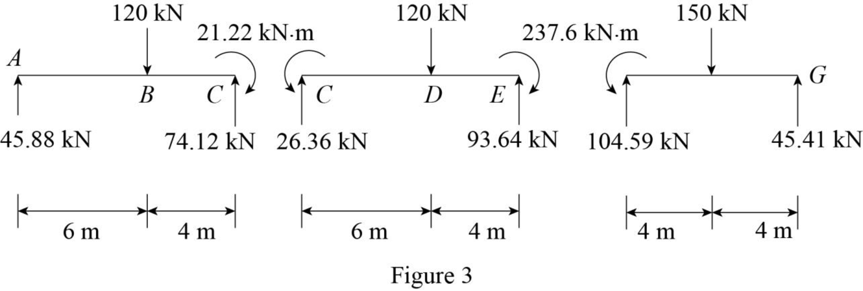
Refer to Figure 3.
Use equilibrium equations:
For span ABC,
Summation of moments of all forces about A is equal to 0.
∑MA=0Cy(10)−21.22−120(6)=0Cy=74.12 kN
Summation of forces along y-direction is equal to 0.
+↑∑Fy=0Ay−120+Cy=0Ay−120+74.12=0Ay=45.88 kN
For span CDE,
Summation of moments of all forces about C is equal to 0.
∑MC=0Ey(10)+21.22−237.6−120(6)=0Ey=93.64 kN
Summation of forces along y-direction is equal to 0.
+↑∑Fy=0Cy−120+Ey=0Cy−120+93.64=0Cy=26.36 kN
For span EFG,
Summation of moments of all forces about E is equal to 0.
∑ME=0Gy(8)+236.7−150(4)=0Gy=45.41 kN
Summation of forces along y-direction is equal to 0.
+↑∑Fy=0Ey−150+Gy=0Ey−150+45.41=0Ey=104.59 kN
Provide the reaction at supports C and E as shown below.
Cy=74.12+26.36=100.48 kNEy=93.64+104.59=198.23 kN
Sketch the reactions for the given beam as shown in Figure 4.
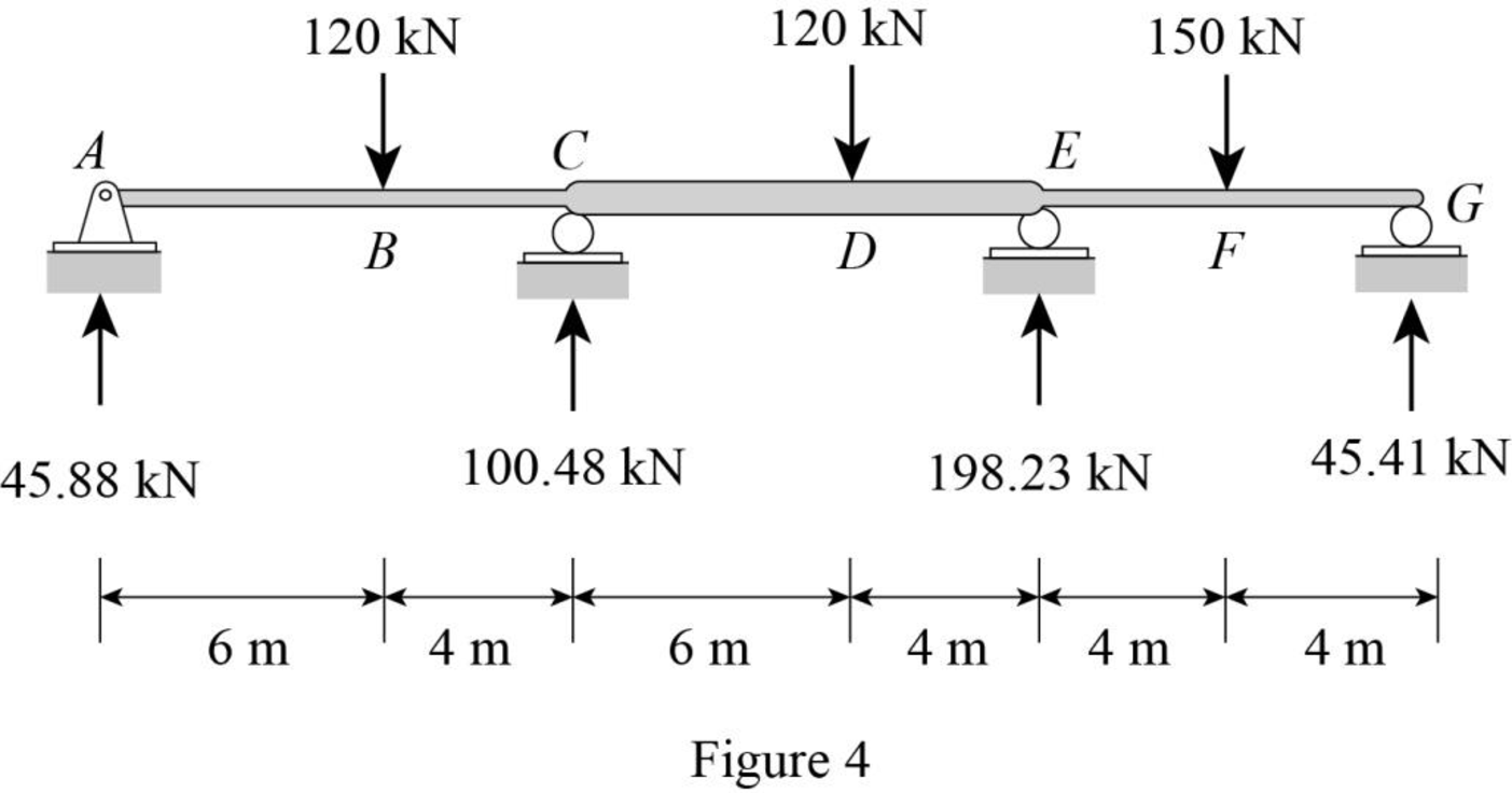
Refer to Figure 4.
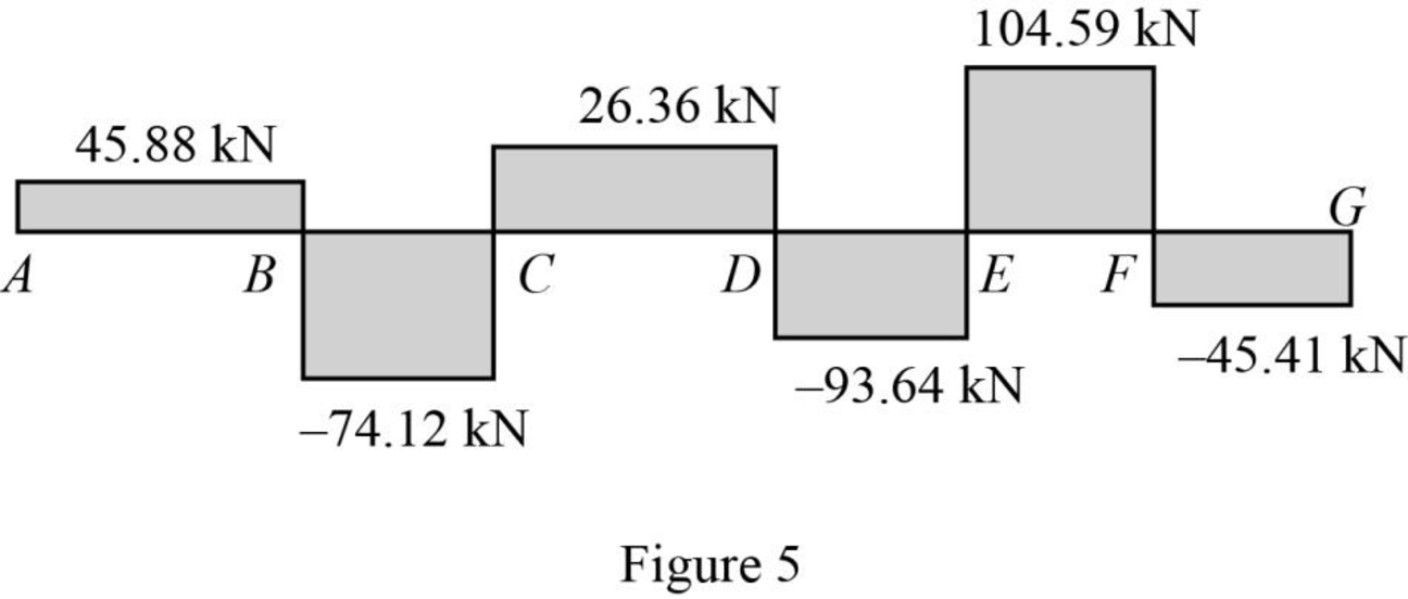
Calculate the shear force (S) for the given beam:
At point A,
SA=45.88 kN
At point B,
SB,L=45.88 kNSB,R=45.88−120=−74.12 kN
At point C,
SC,L=45.88−120=−74.12 kNSC,R=45.88−120+100.48=26.36 kN
At point D,
SD,L=45.88−120+100.48=26.36 kNSD,R=45.88−120+100.48−120=−93.64 kN
At point E,
SE,L=45.88−120+100.48−120=−93.64 kNSE,R=45.88−120+100.48−120+198.23=104.59 kN
At point F,
SF,L=45.88−120+100.48−120+198.23=104.59 kNSF,R=45.88−120+100.48−120+198.23−150=−45.41 kN
At point G,
SG,L=45.88−120+100.48−120+198.23−150=−45.41 kNSG=45.88−120+100.48−120+198.23−150+45.41=0
Sketch the shear diagram for the given beam as shown in Figure 5.
Refer to Figure 4.
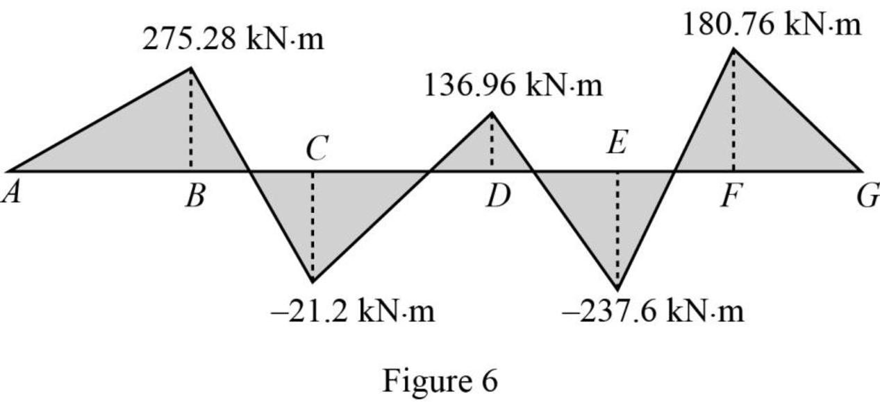
Calculate the bending moment (M) for the given beam:
At point A,
MA=0
At point B,
MB=45.88(6)=275.28 kN⋅m
At point C,
MC=45.88(10)−120(4)=−21.2 kN⋅m
At point D,
MD=45.88(16)−120(10)+100.48(6)=136.96 kN⋅m
At point E,
ME=45.88(20)−120(14)+100.48(10)−120(4)=−237.6 kN⋅m
At point F,
MF=45.88(24)−120(18)+100.48(14)−120(8)+198.23(4)=180.76 kN⋅m
At point G,
MG=0
Sketch the bending moment diagram for the given beam as shown in Figure 6.